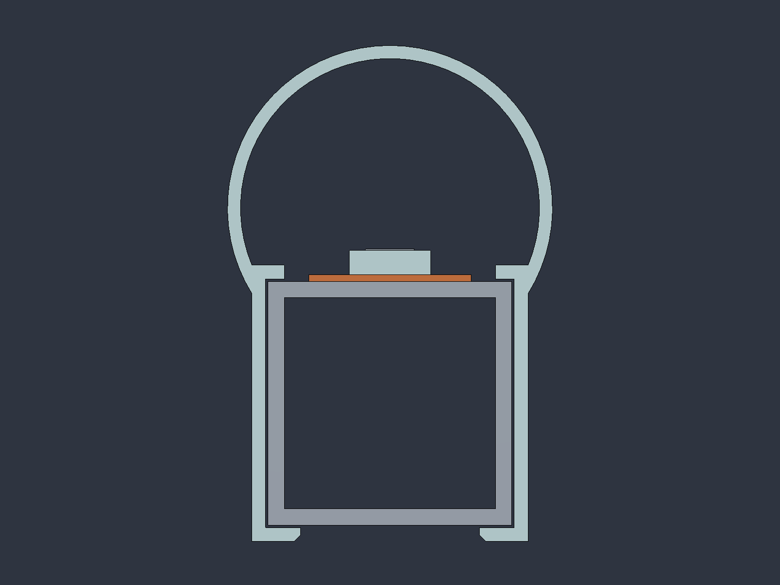
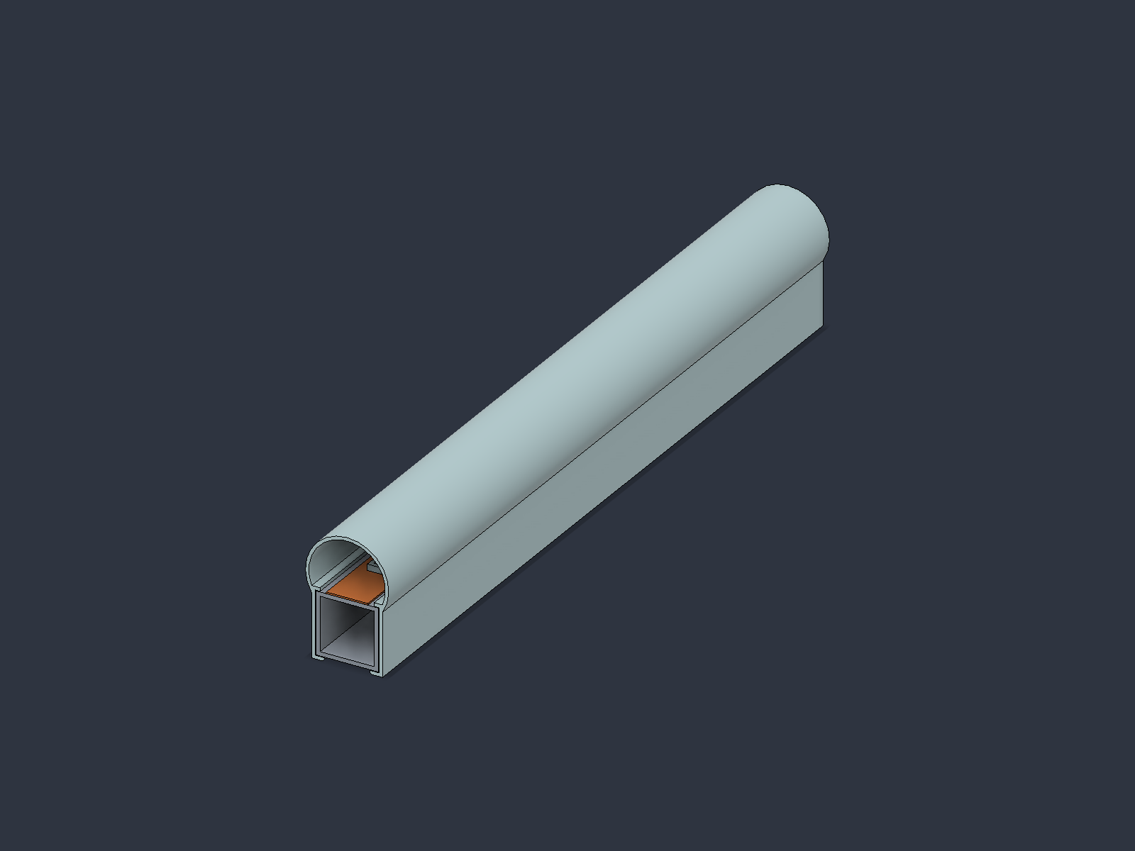
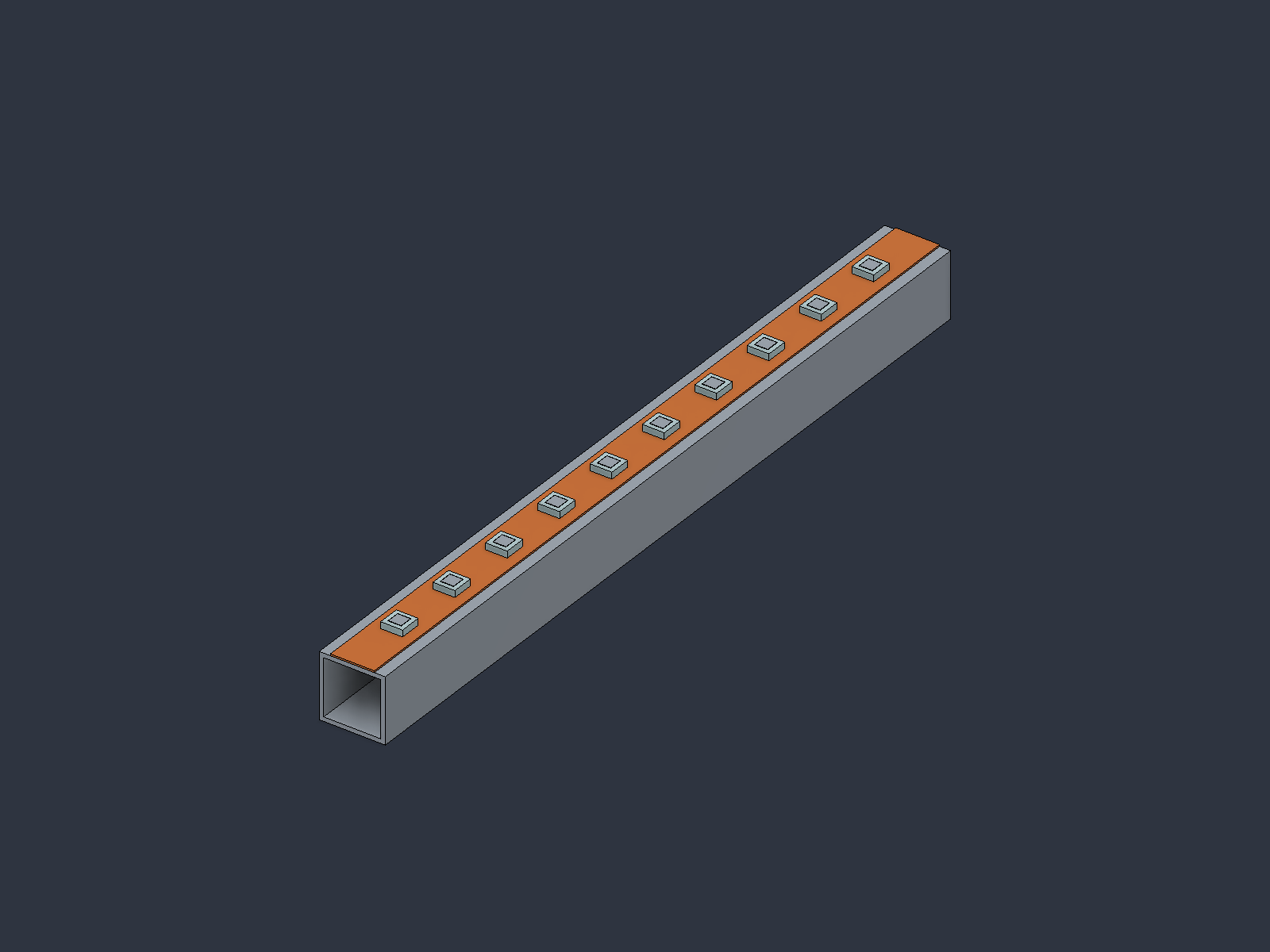
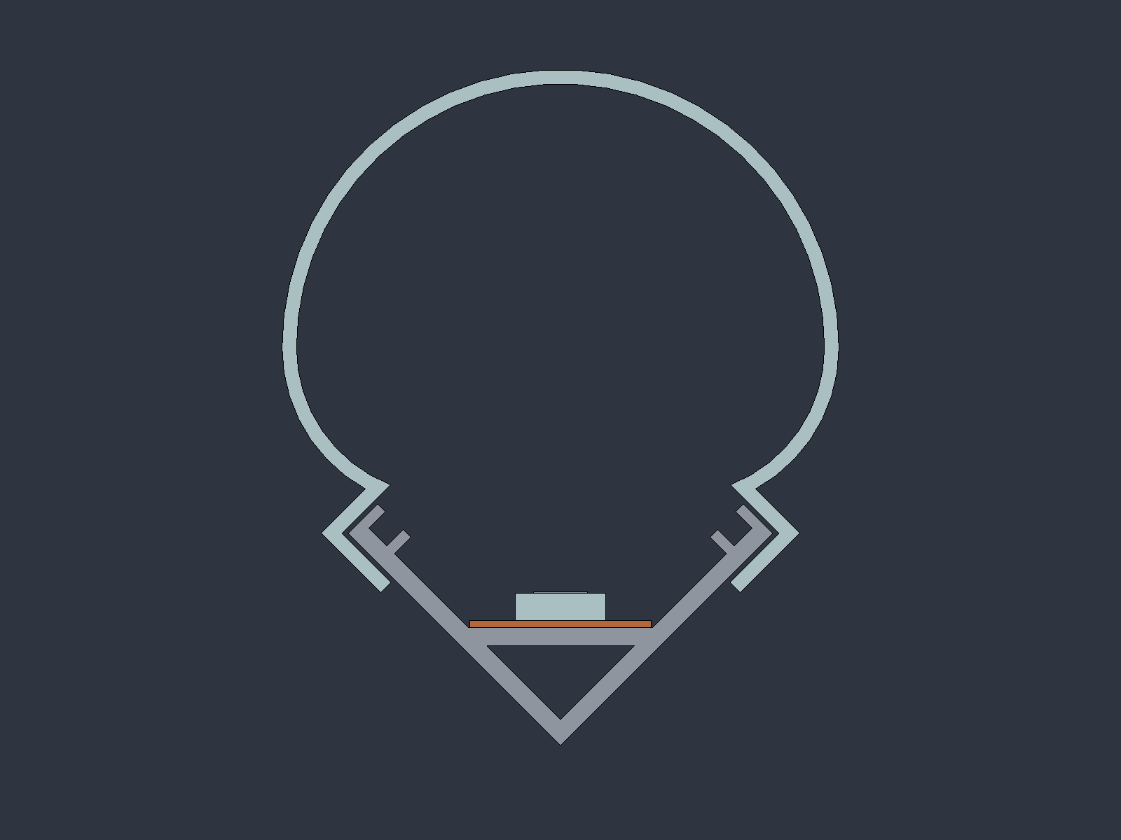
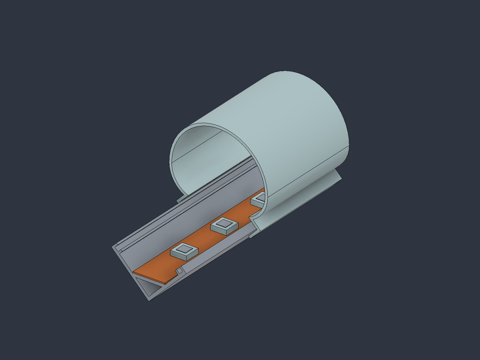
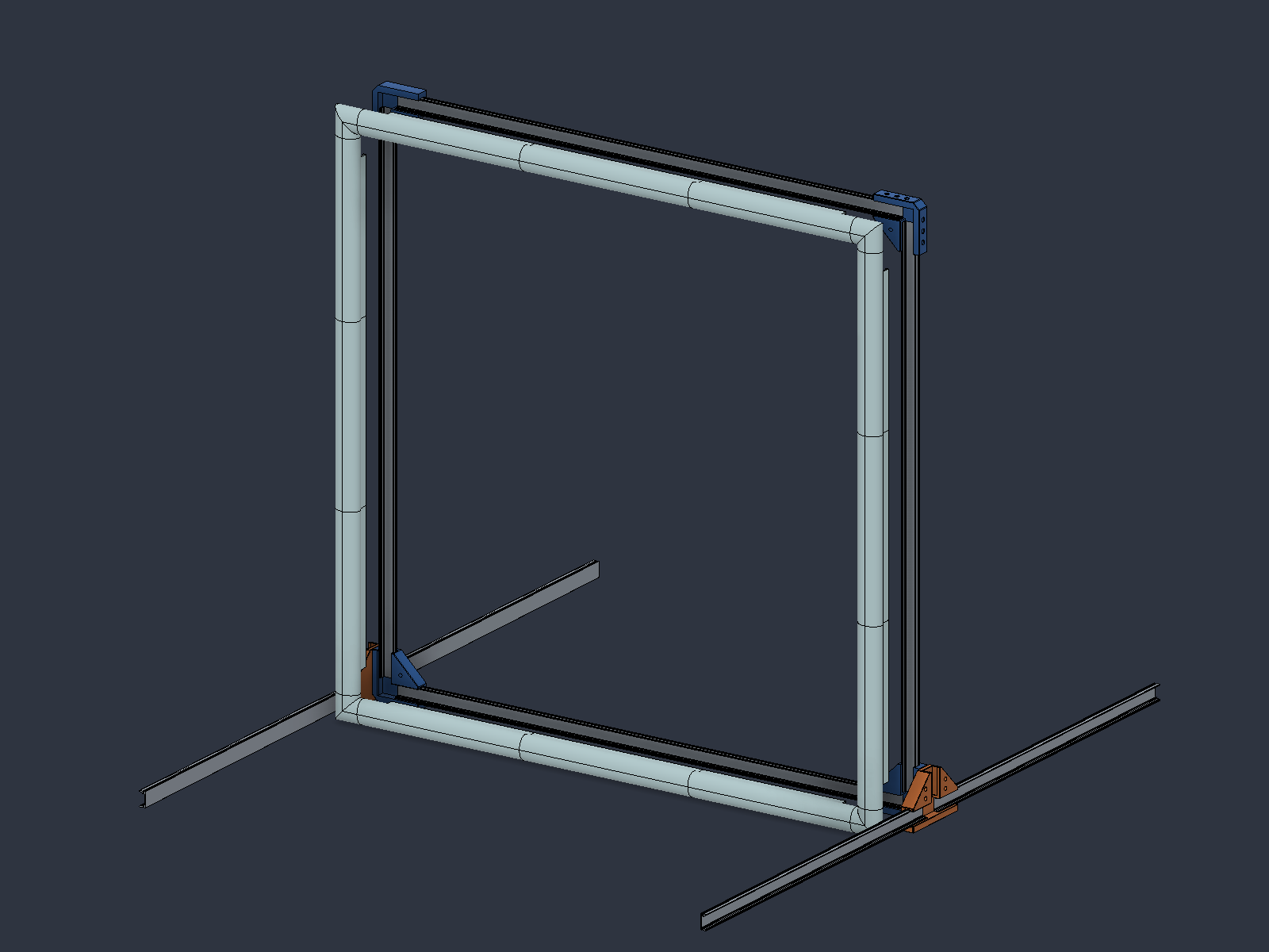
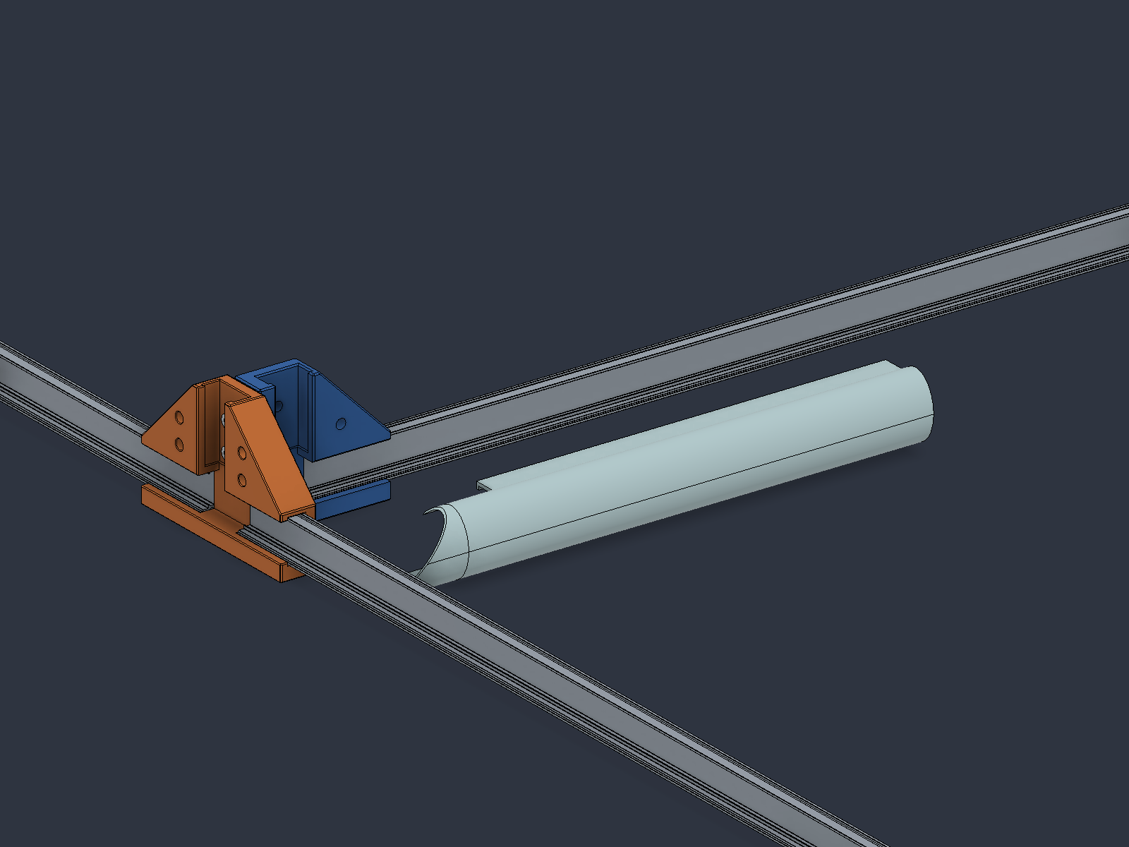
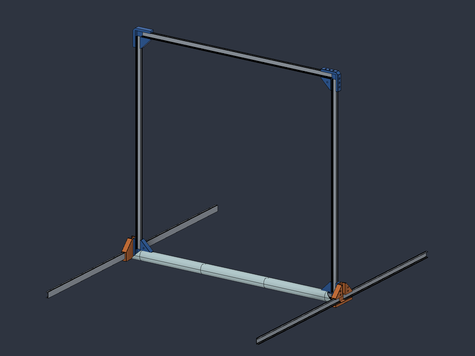
First study of the closed 15 × 15 × 1 mm tube as the structural rail, with the LED strip on a flat face and a wraparound clip diffuser in 180 mm modules. The current parts above grew out of it.
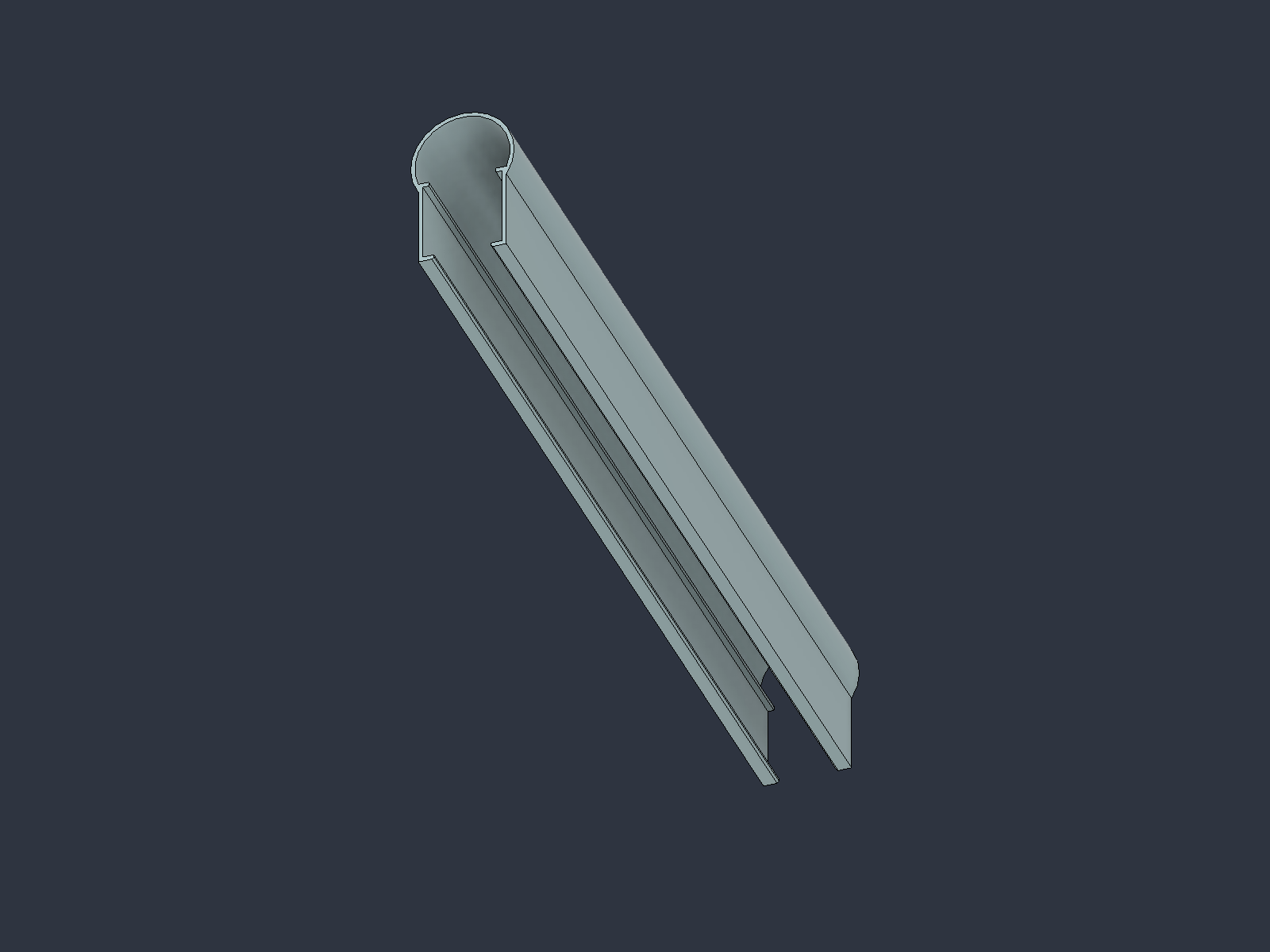
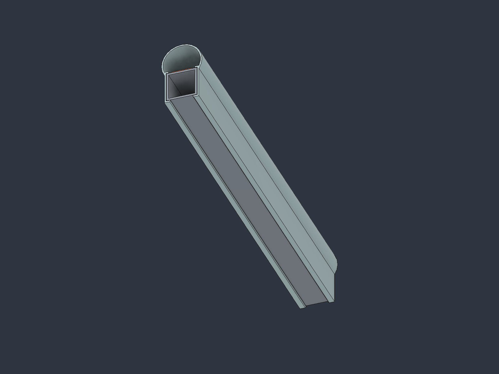
Wraparound clip sectionThe owner-designed 20 mm round light chamber sits in front of the 15 mm tube. Continuous rear hooks retain the cover; orange marks the LED-strip PCB.Continuous light surfaceA 180 mm module retains the original 0.8 mm optical wall. The cover widens beyond the tube, while its arms reach around the sides.Continuous retaining edgesThe rear hooks run the full module length. The same 2D section is extruded throughout, avoiding intermediate steps when printed upright.Retained behind the tubeThe rear hooks overlap the tube edges. Wider illuminated shoulders may remain visible from behind; actual glow and snap performance still need a physical test.WS2812 strip on a flat face5050 housings and optical windows are shown at 16.67 mm pitch for 60 LEDs per meter. PCB dimensions and package height are illustrative.
V profile · dropped
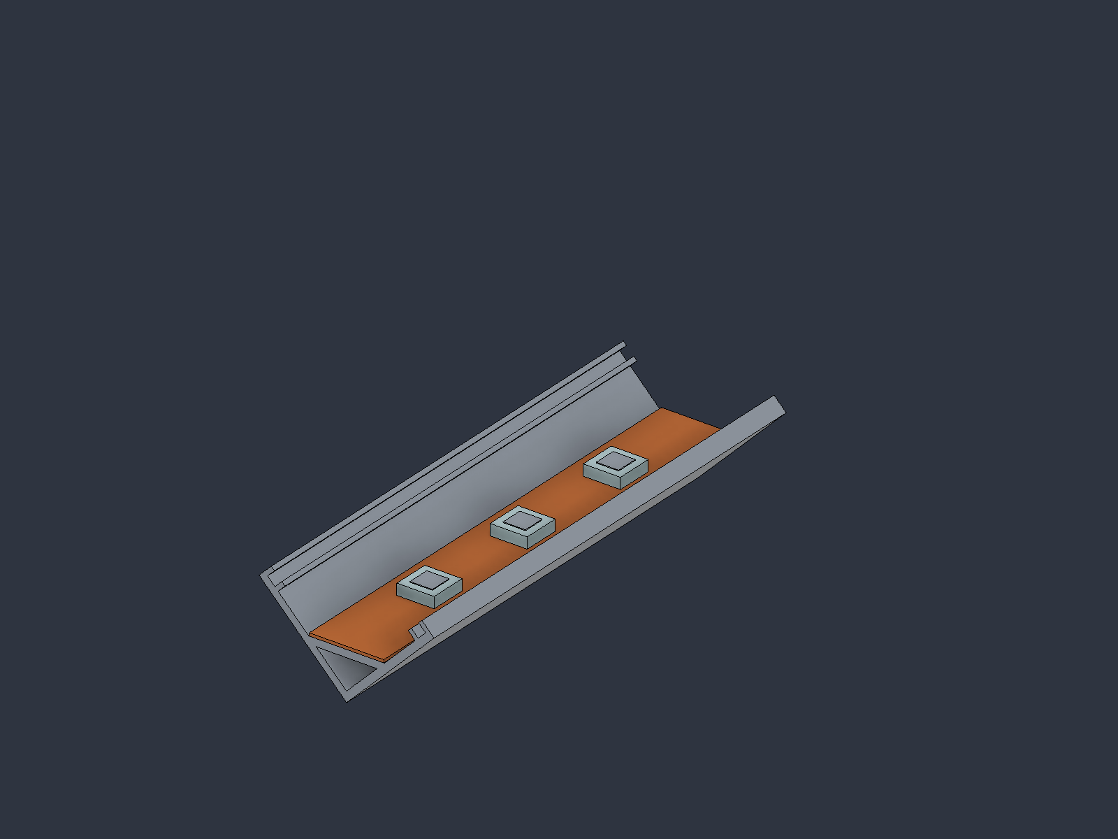
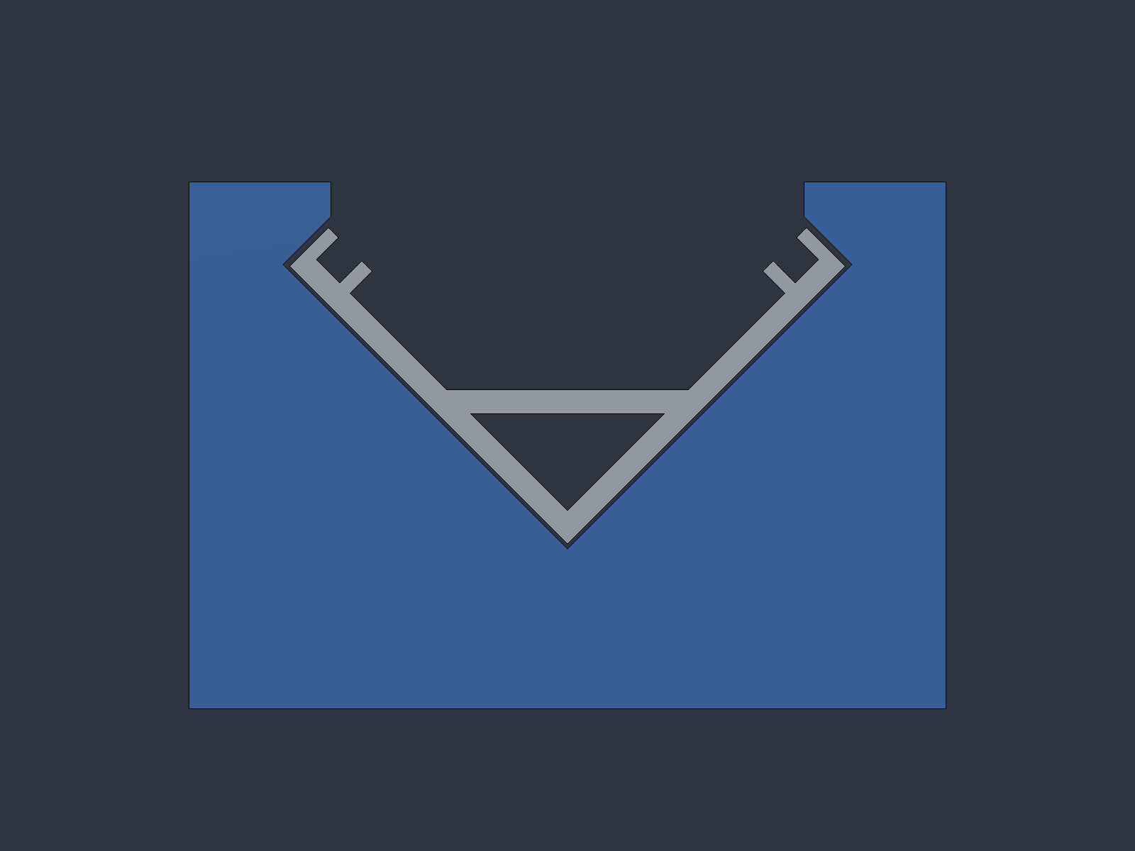
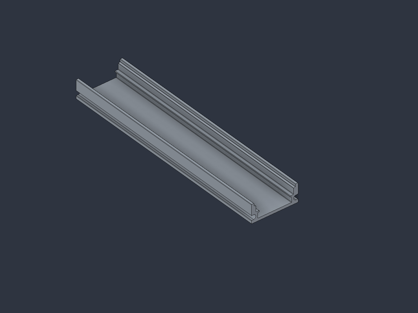
Jopassy V-profile rail with a closed triangular chamber under the LED bed. CAD only; dropped in favor of the square tube. The wide metal section also hid the diffuser from behind.
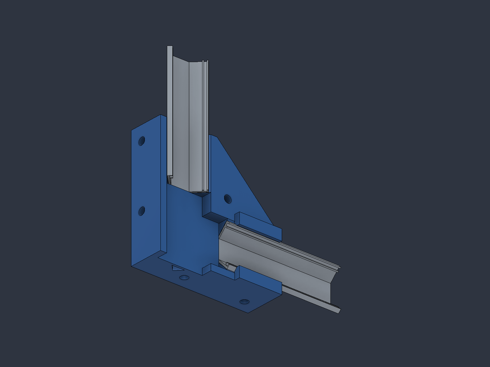
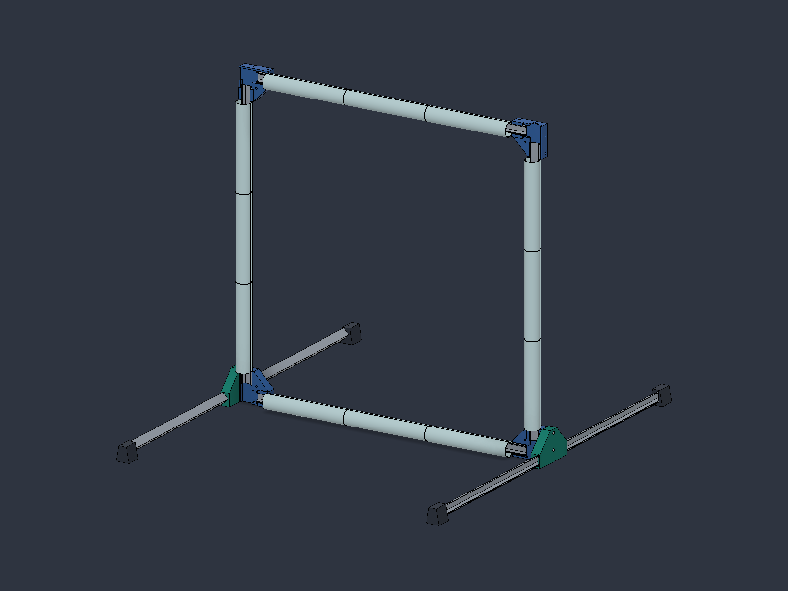
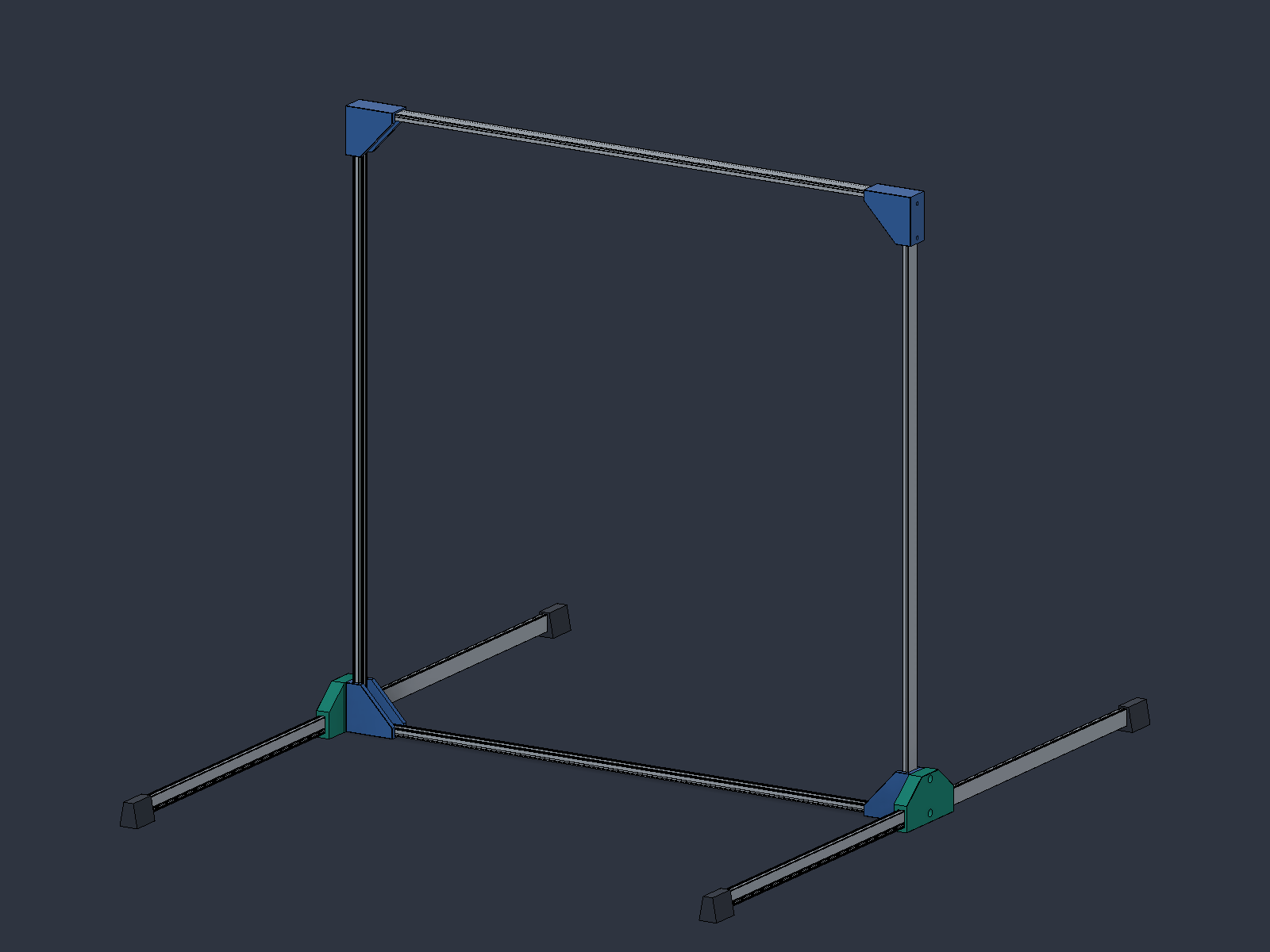
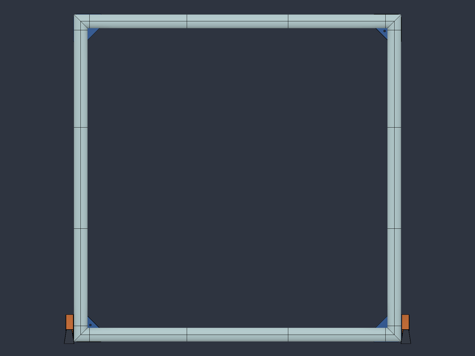
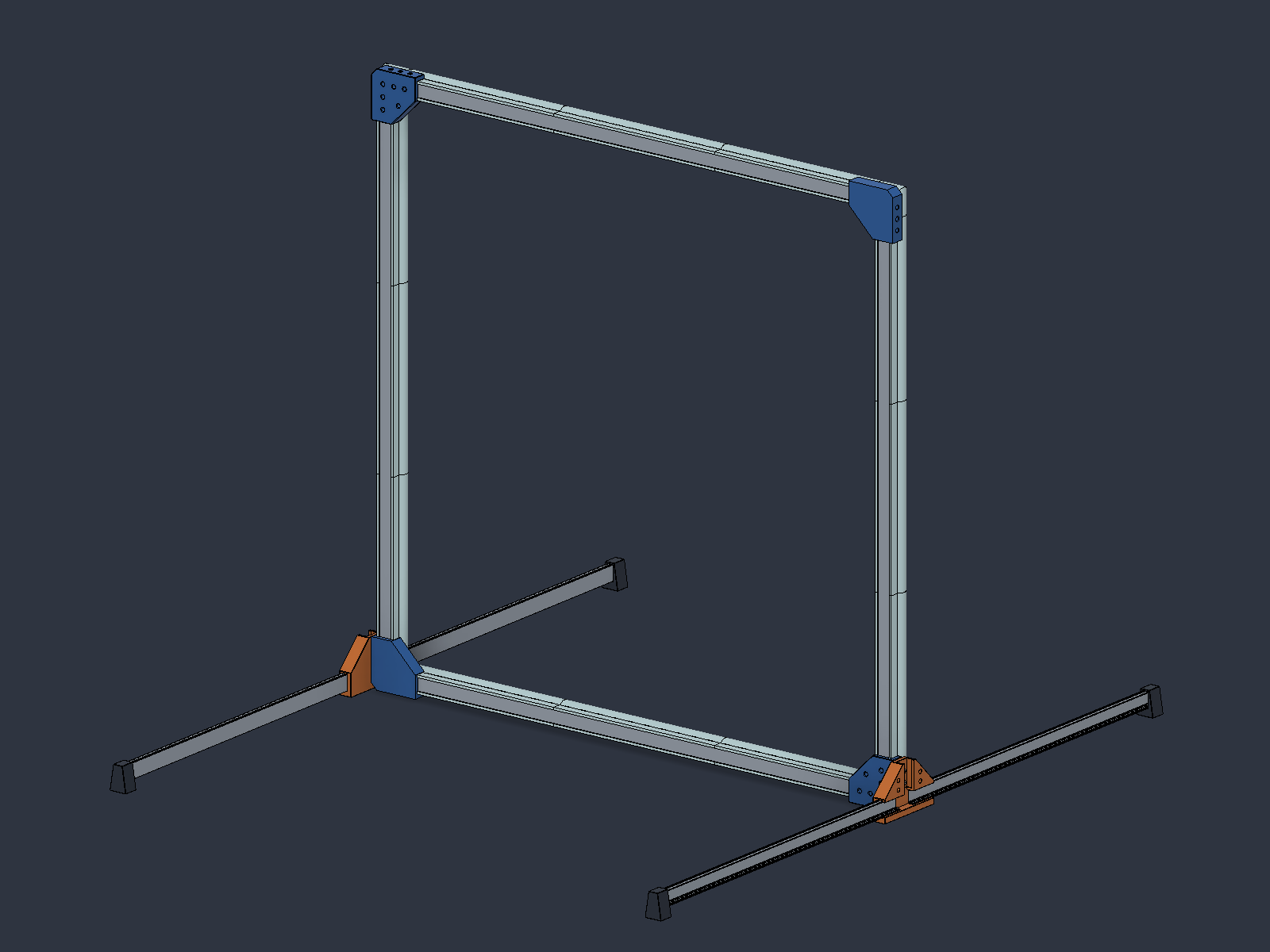
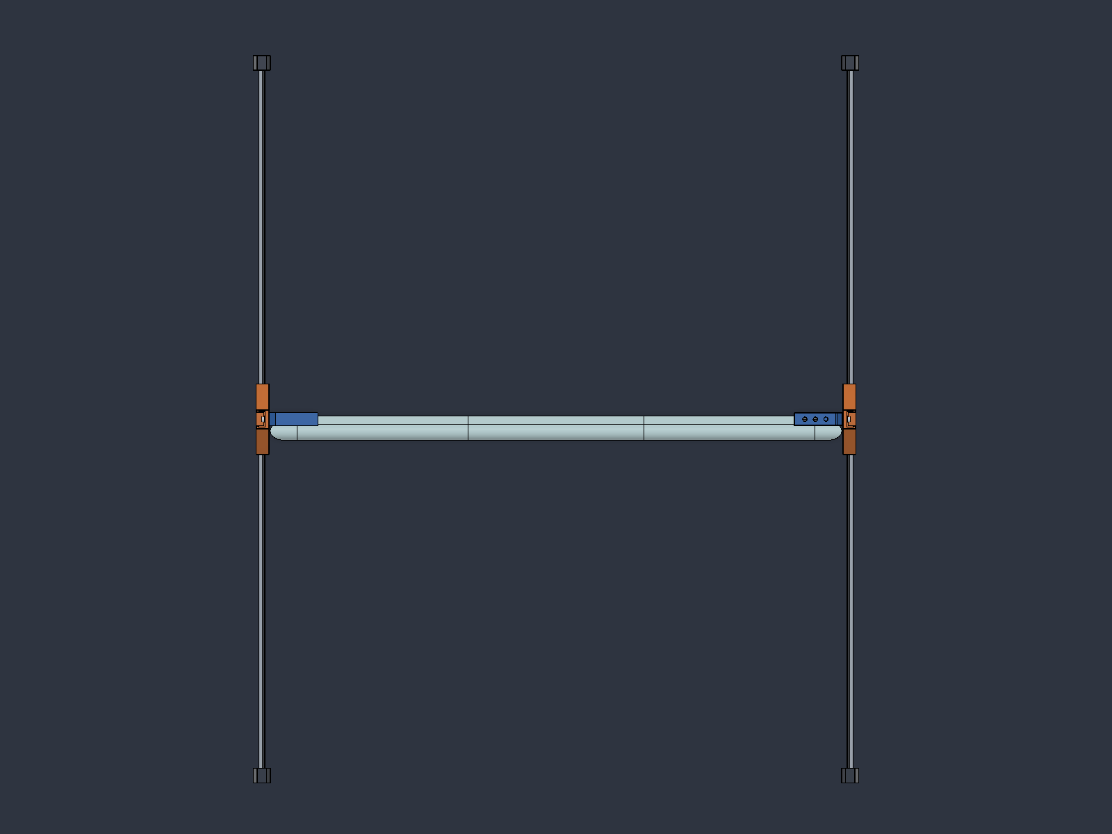
LED strip on the V-profile bedThe strip lies on the flat LED support above the closed triangular cell. Packages remain below the upper clip rims.V-profile retentionContinuous F-shaped rims sit beneath the matched retaining lips. Final fit awaits the real extrusion.Profiles in the cornerAxial insertion under the retaining lips; a solid junction continues the flat LED support.Three-way junctionThe T connector provides the shared crossbar junction for stacked gates.Diffuser cross-sectionThe 0.8 mm balloon wall wraps around both outer F-rim corners. Clip retention and rear glow need physical tests.Diffuser over the V profileA continuous extruded section returns along the outside flanks, with 0.25 mm nominal clearance around the rims.V-profile gate layoutAssembly overview with four feet; mechanical stability has not yet been tested.
U profile · dropped after testing
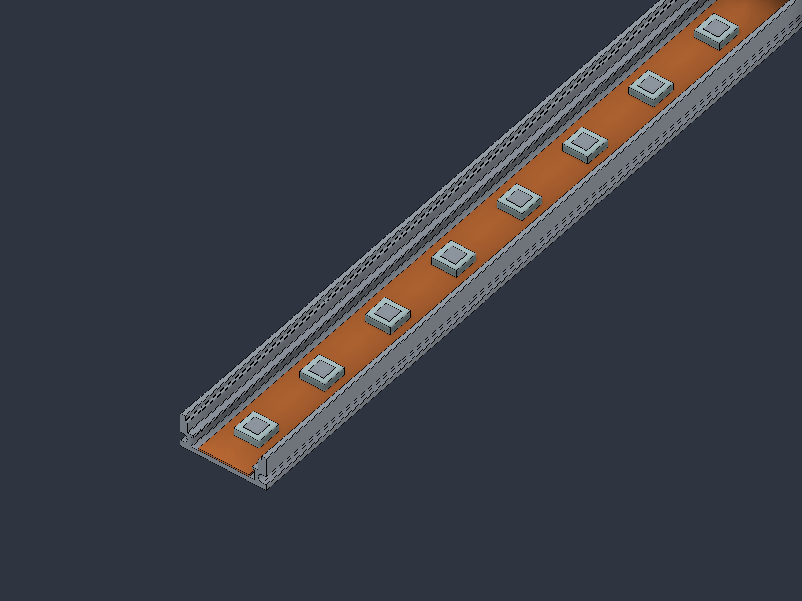
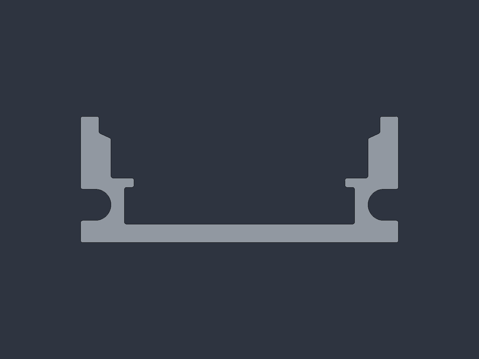
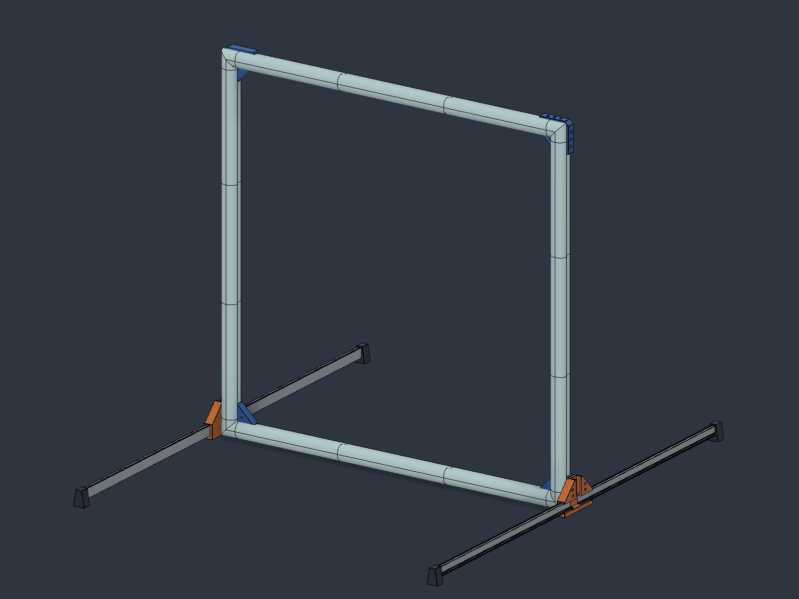
Shallow U-profile LED rails, first with the LEDs facing forward, then rotated 90° toward the opening. Both prototypes were built; the rails twisted too easily and the gate did not stand rigidly.
LED strip inside the U railThin PCB and 5050 packages on the original LED bed; 16.67 mm spacing represents 60 LEDs per meter.Original U profileAn open, shallow section carries the LED strip.Original gate layoutPrinted connectors, segmented diffusers and four offcut feet. CAD illustration of the tested concept.U profile rotated by 90°The LEDs face the opening. This variant was also built and tested.Inward-facing U-profile frameCAD layout with dedicated foot brackets. The physical prototype remained too flexible.
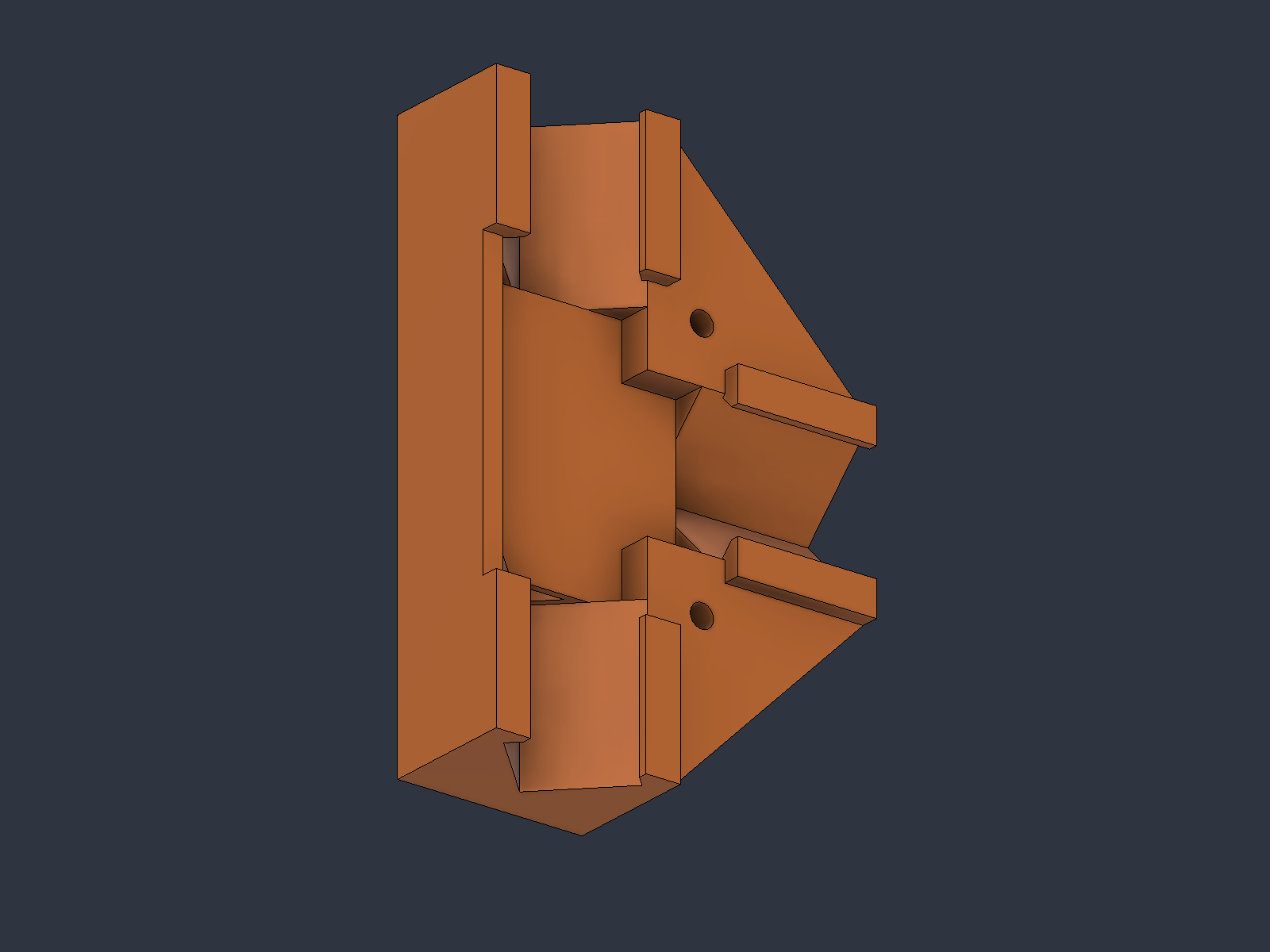
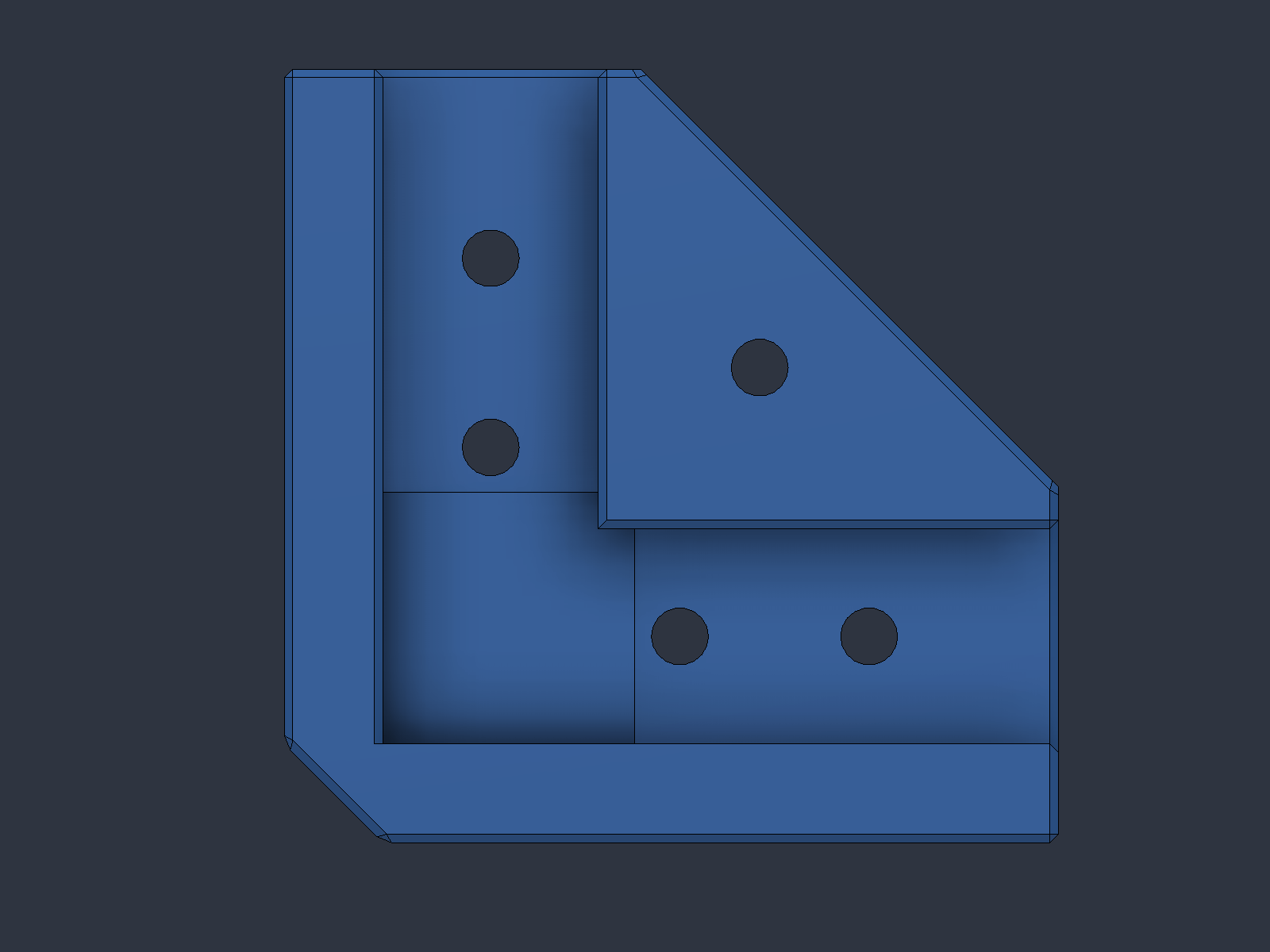
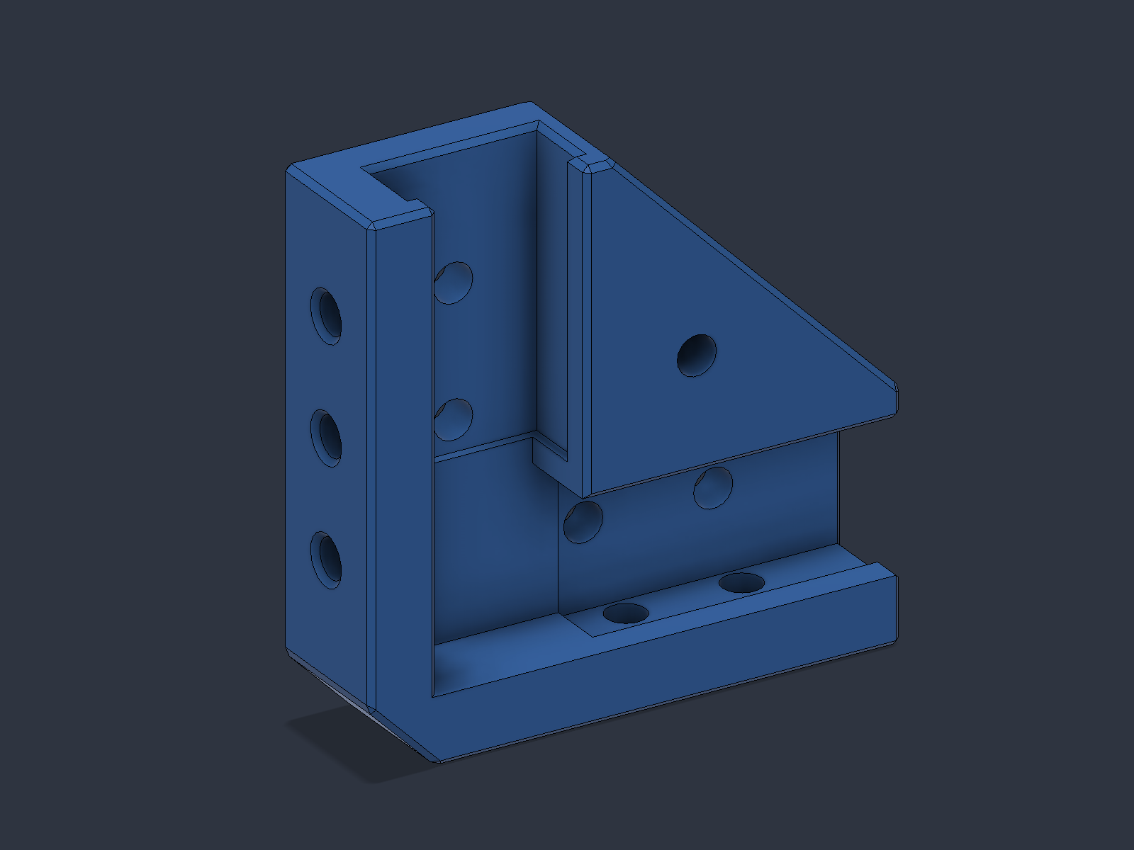
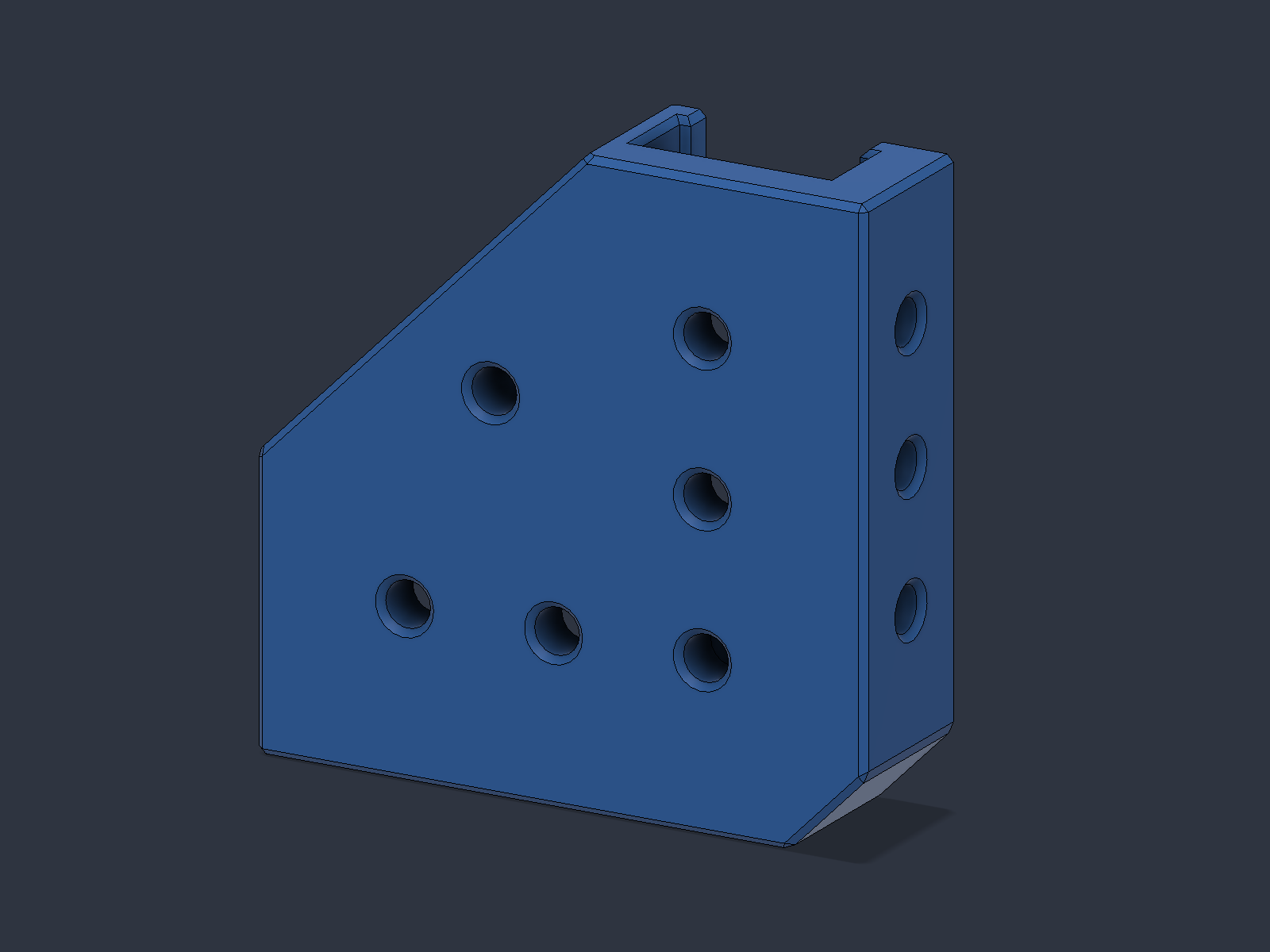
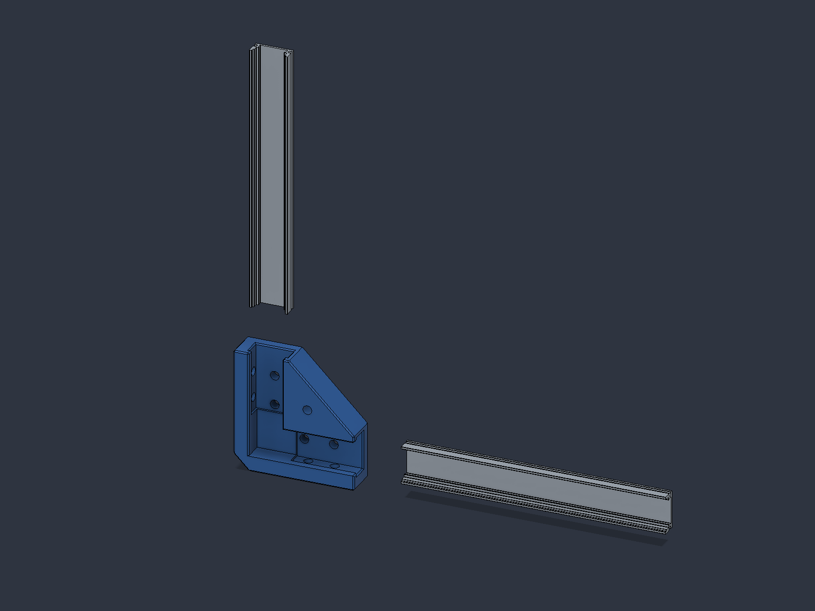
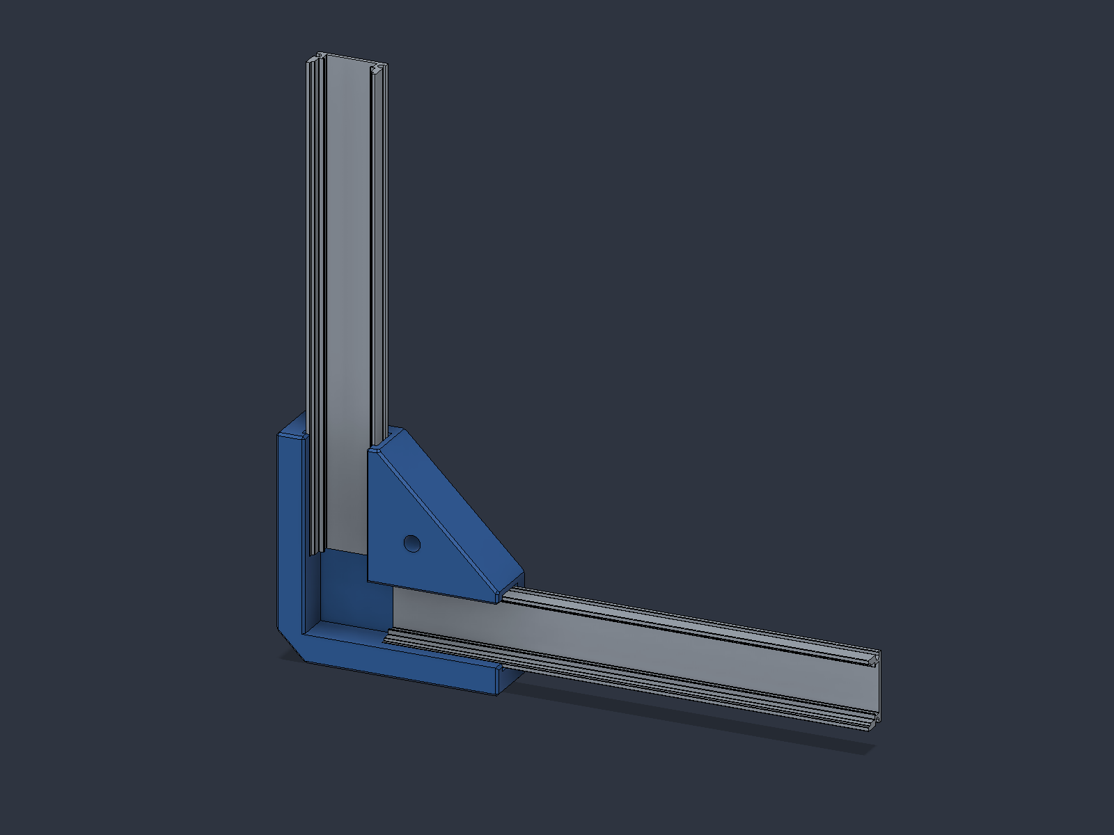
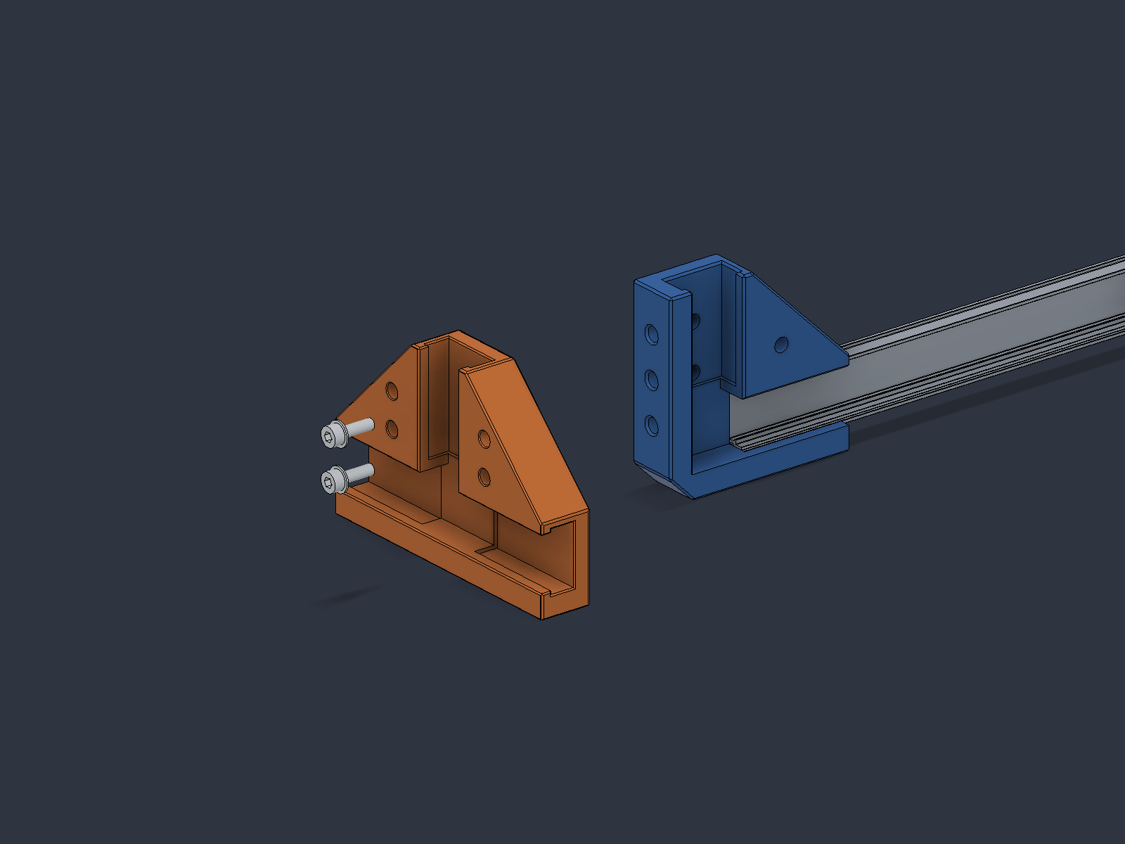
90° connector Two perpendicular sockets form a frame corner.Profile sockets The aluminum sections slide into the printed connector.Rear and mounting holes Holes provide attachment points for M3 heat-set inserts.
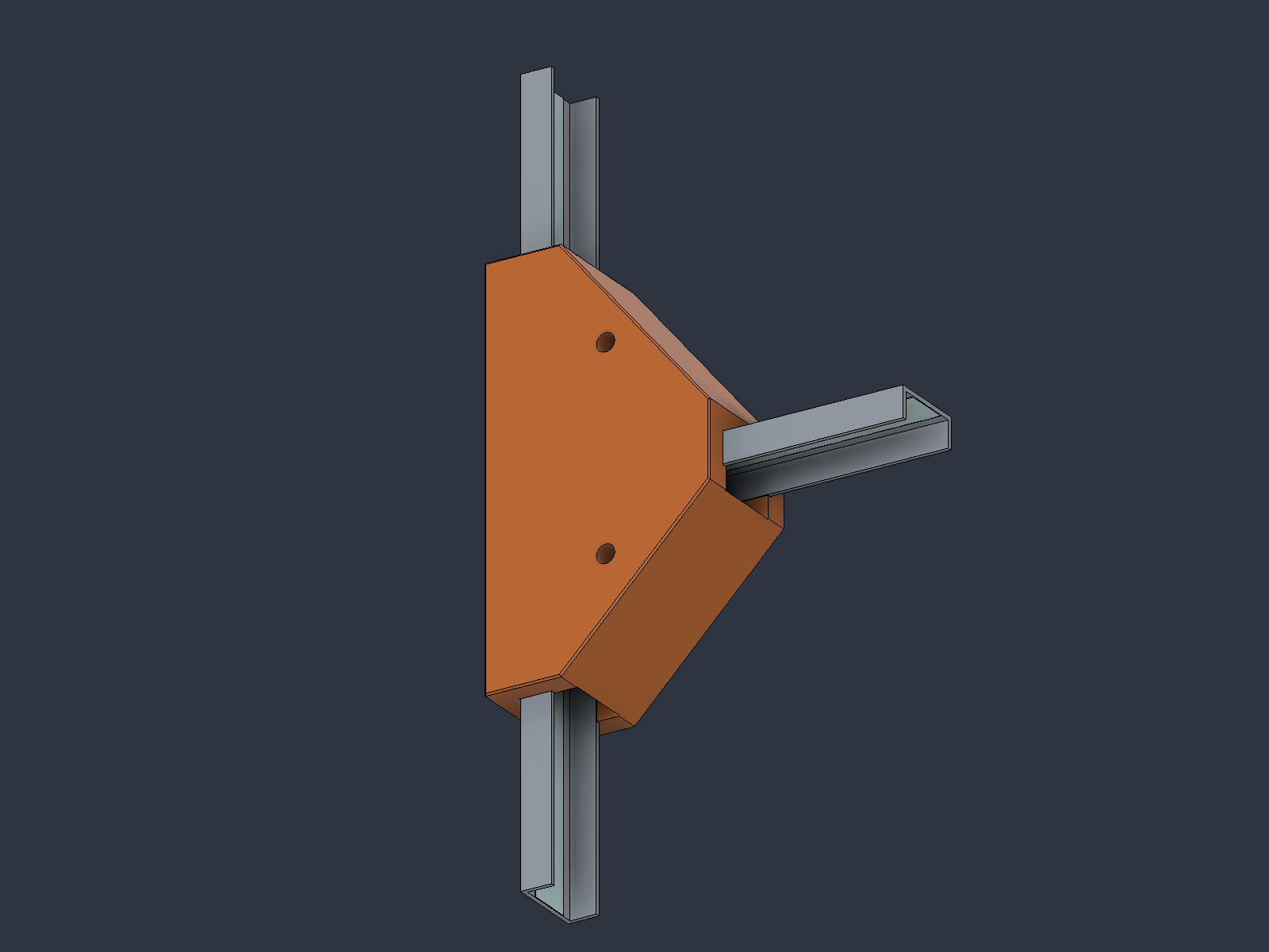
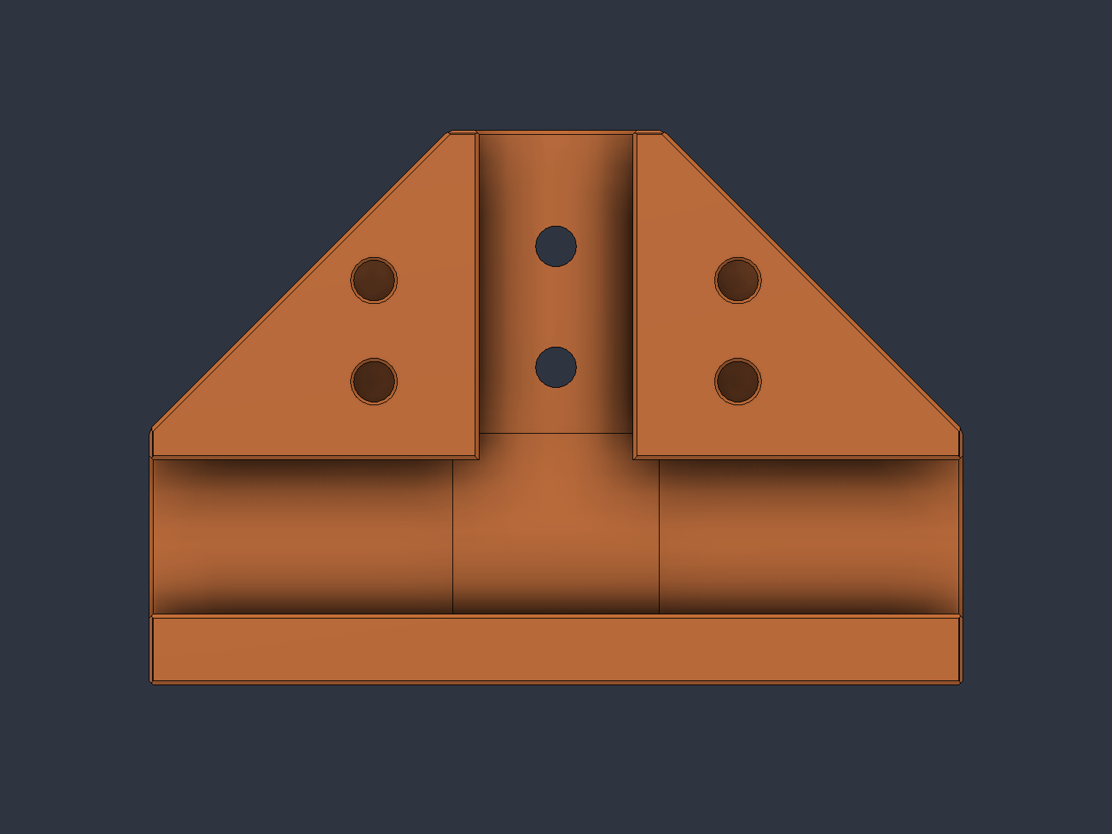
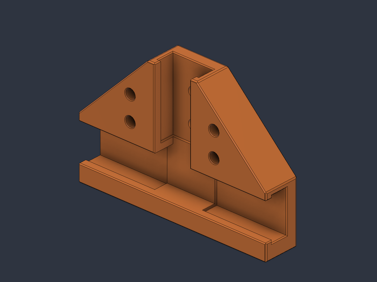
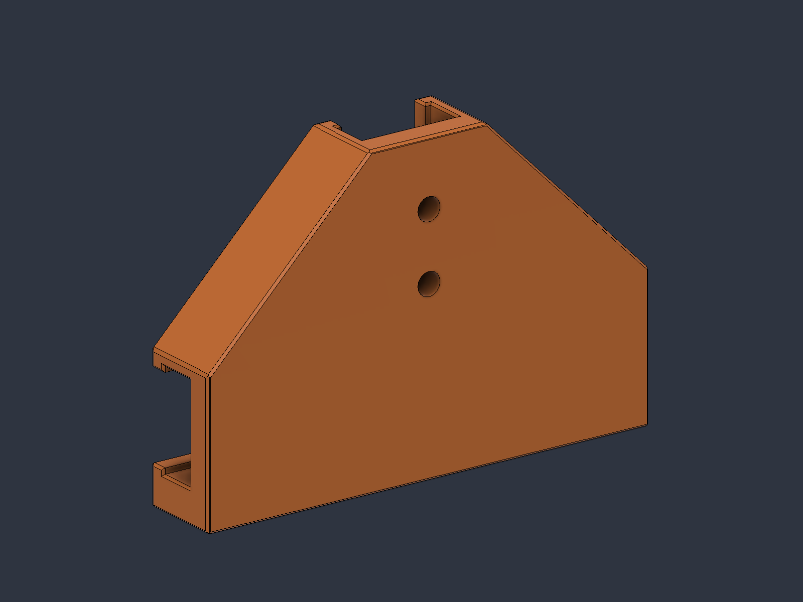
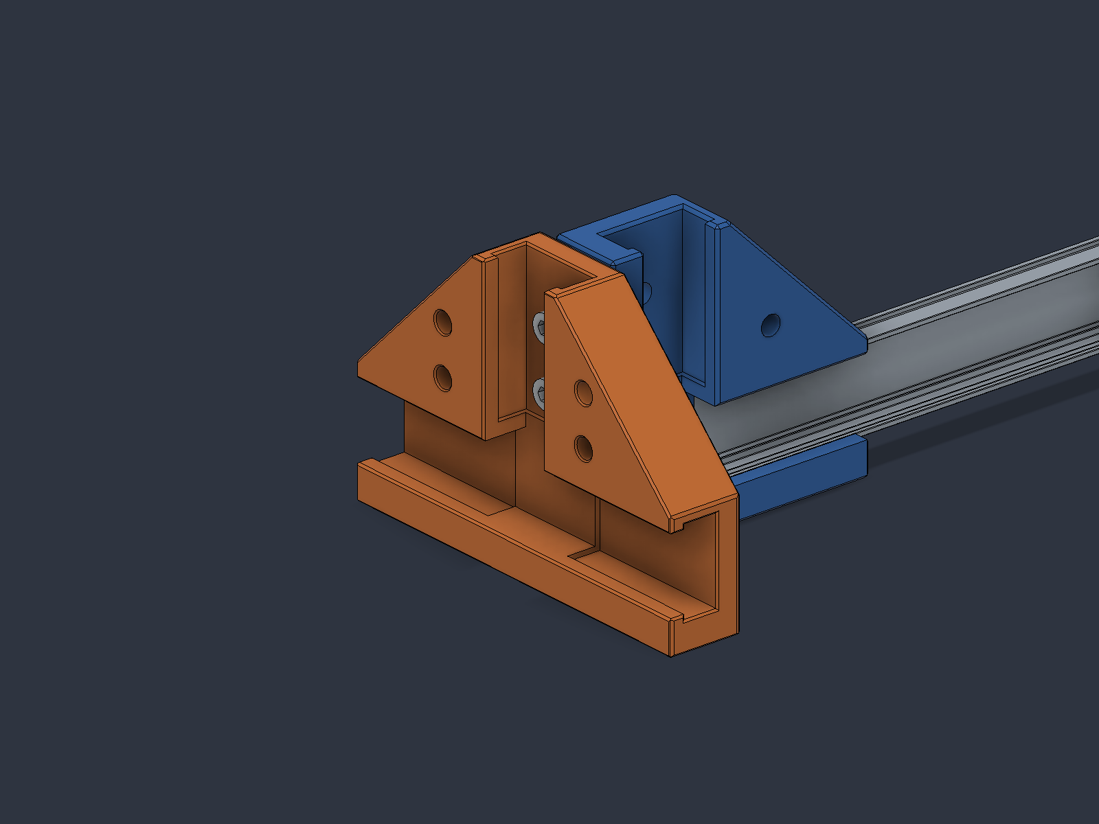
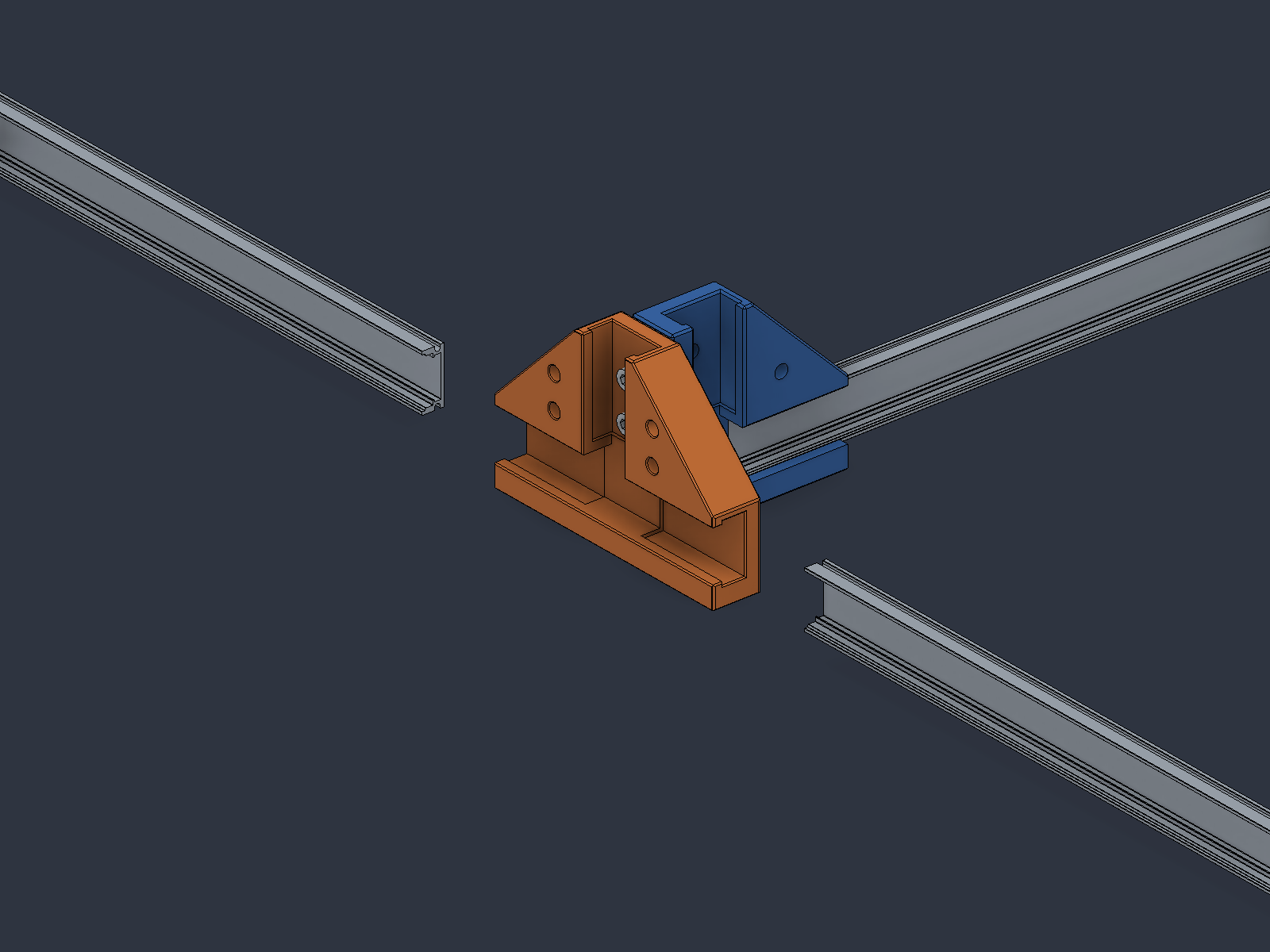
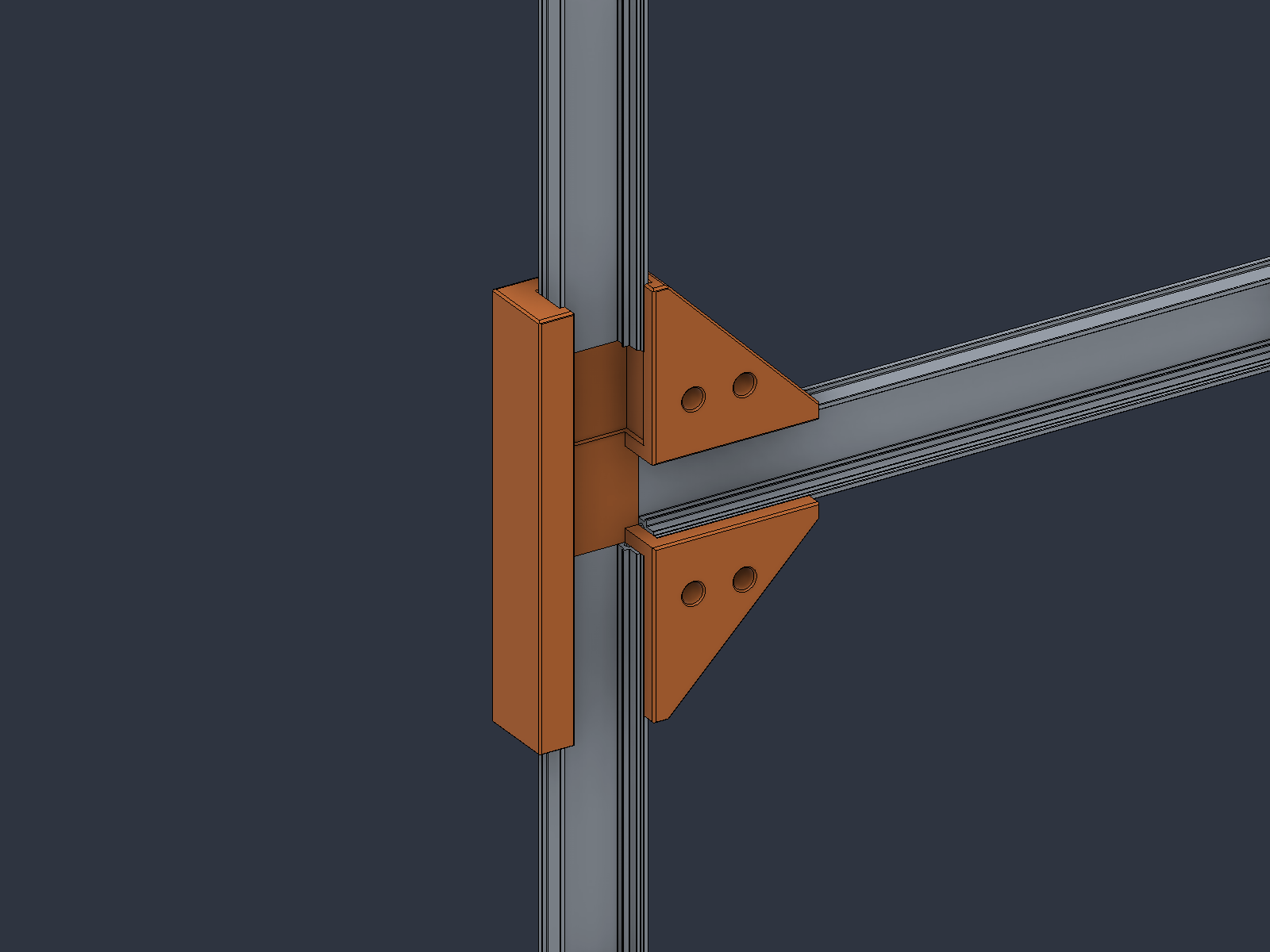
T connector The same three-way part serves as a foot holder or frame junction.Open center The central passage leaves room for cable routing.Mounting face Two upper holes align with the corner connector.
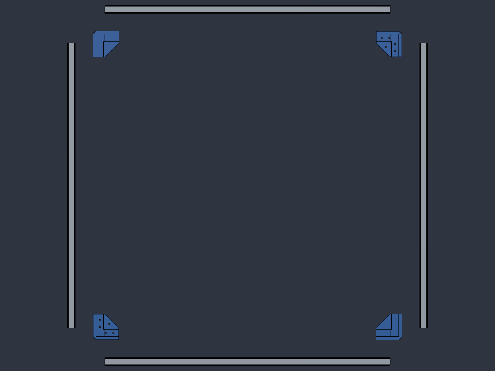
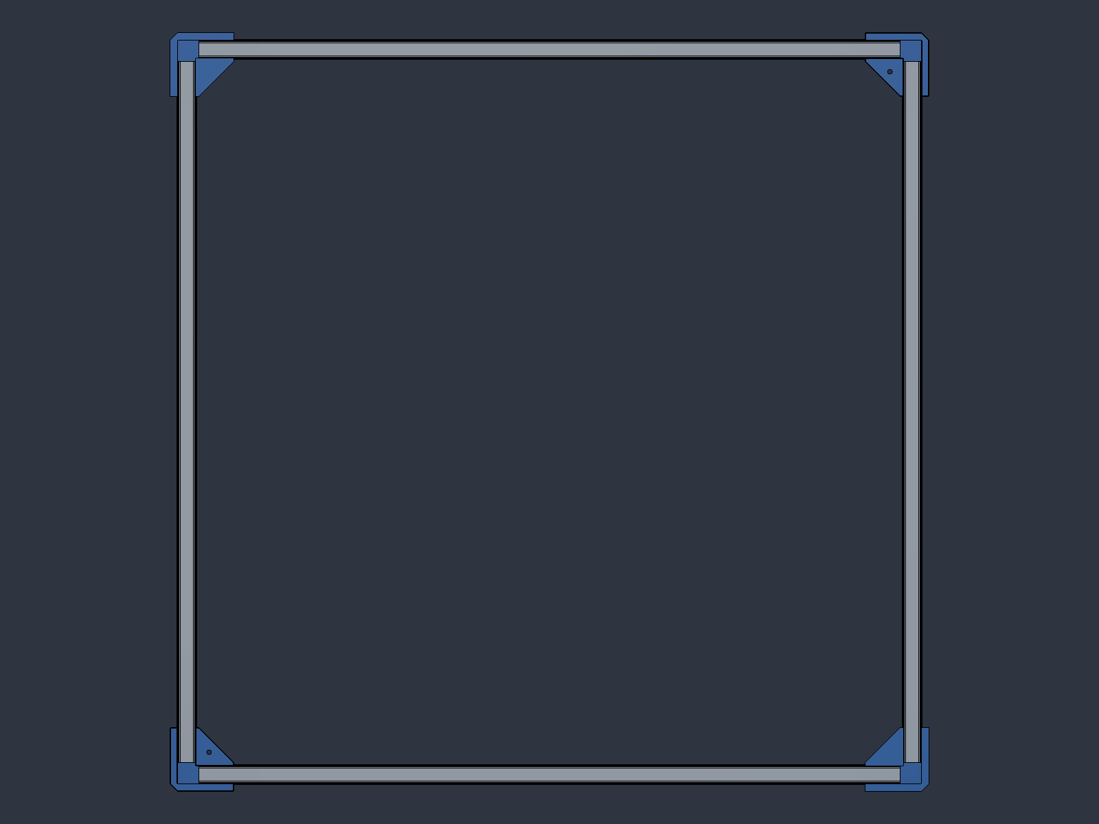
Insert the profiles Push both aluminum sections into the corner sockets.One assembled corner The profiles meet at the printed connector.Four corners, four profiles Arrange the frame parts before closing the square.Closed frame Four 600 mm sections form one gate.
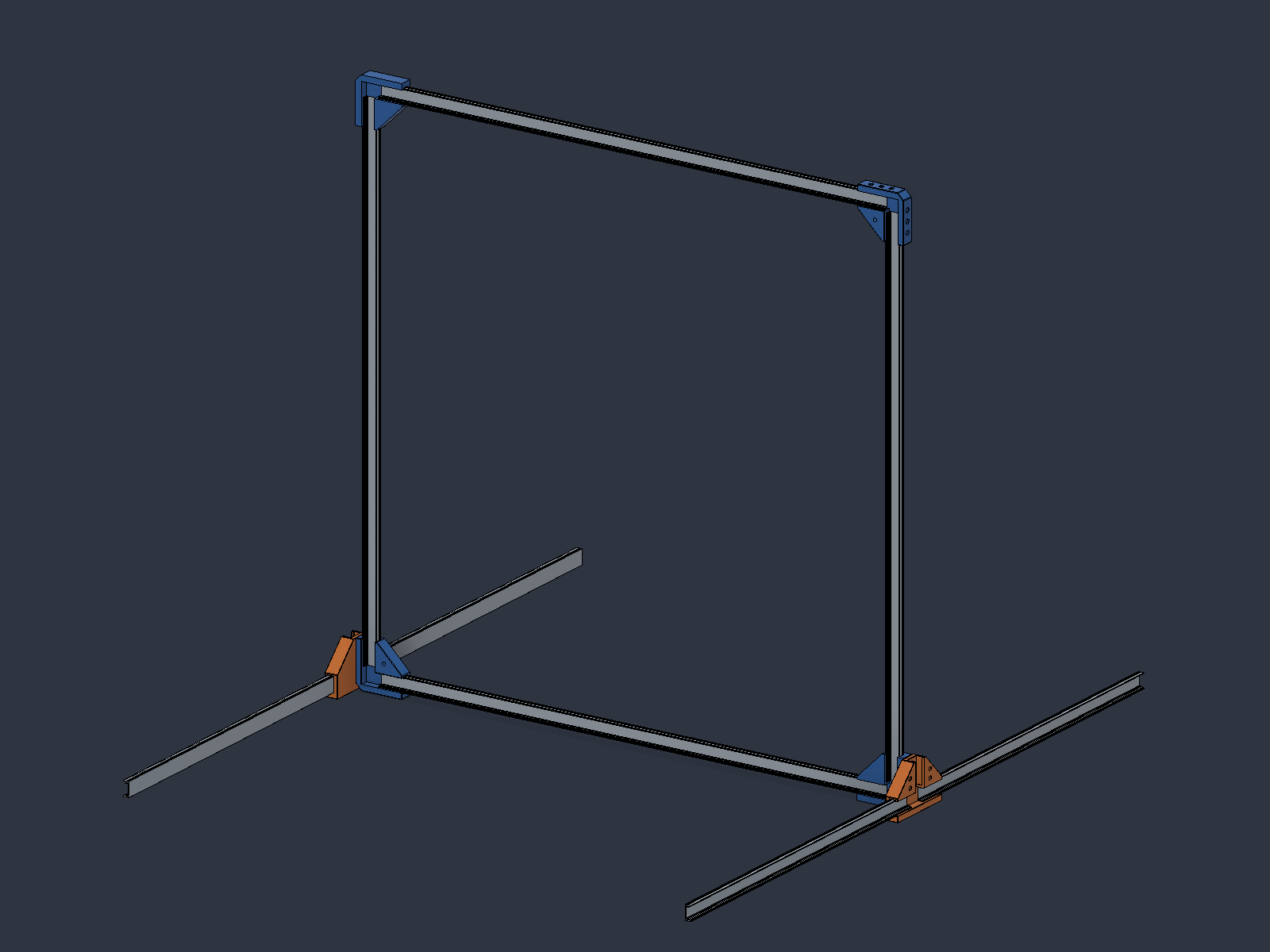
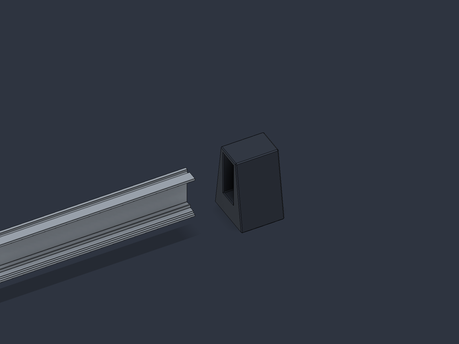
Each 1 m profile supplies a 600 mm gate bar and a roughly 400 mm foot offcut. The feet stand on edge for stiffness.
Attach the foot holder Bolt the T connector onto the outside of the lower corner.Two M3 screws Two upper screws and washers hold the T connector.Insert the feet One 400 mm offcut extends forward, the other backward.Four feet Both sides reuse the same T connector component.
Add the diffusers The segmented covers approach the frame from the front.Clip-on detail A printed diffuser segment clips over the aluminum profile.Bottom bar covered Three approximately 200 mm segments cover one bar.
Incoming-drone view The LED-facing side points toward the approaching drone.Complete gate A square illuminated frame with forward and rear supports.Rear view The aluminum frame remains visible behind the diffusers.Foot layout The top view shows the four opposing support sections.
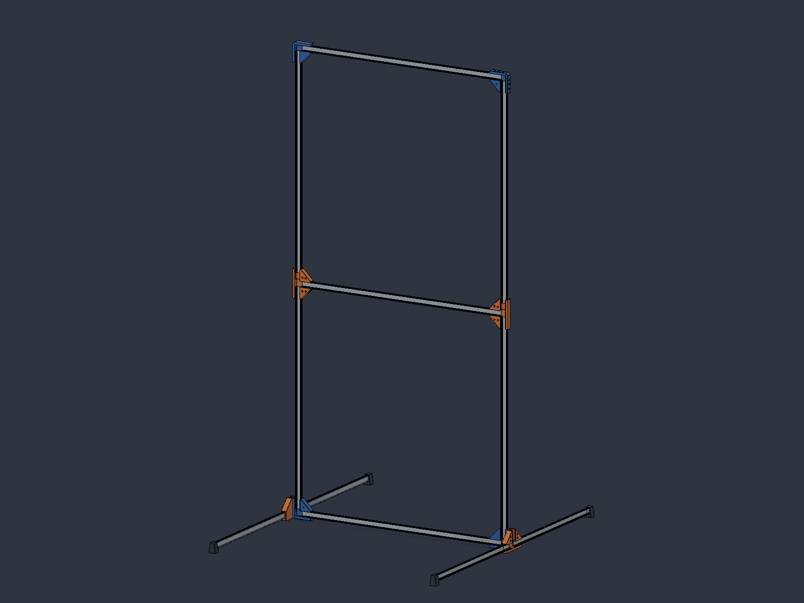
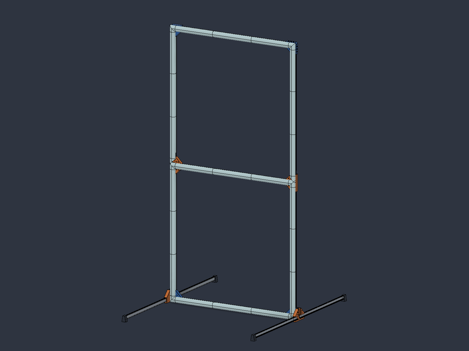
The T connector also links two stacked frames. Diffuser details at the shared junction still need refinement.
Stacked frame Two T junctions replace the upper corners at the shared bar.Shared T junction Upper and lower uprights meet the horizontal crossbar.Double-gate concept Two gates share one horizontal bar and the same foot system.