Modular Tinywhoop LED Gate
Published: 02 Oct 2026 · Updated: 06 Nov 2026
Newest CAD parts (corner CR6.7, foot bracket FB6.3, DF6 diffusers) with the placeholder controller box · Open full screen · Offline package (31 MB)
A modular Tinywhoop racing gate made from aluminum tubes and printed parts. Around the frame, the project explores wireless LED control with GateLink, race-event integration and interactive 3D assembly tools.
Current status · 5 November 2026
The full illuminated single gate and the towers still need validation; physical inventory is being reconciled.
| Part | Current version | Status |
|---|---|---|
| Frame | 15 × 15 × 1 mm aluminum tube, 600 mm | Gate size not final |
| Corners | 90° corner CR6.7 with a 45° inner fill, printed on that fill | CAD only; predecessor CR6.4 printed and fits FB6.2 |
| Corner cover | CC2.3, one countersunk M3 from the front | CAD only |
| Diffuser | Clip-on DF6 rail set, three pieces per rail | CAD only; predecessor DF5 printed, too tight behind the tube |
| Feet | Foot bracket FB6.3 with a 60° clip catch, end cap v2, 330 mm legs | FB6.2 (55° catch) printed and fits; end cap fit OK; FB6.3 open; 330 mm legs ordered |
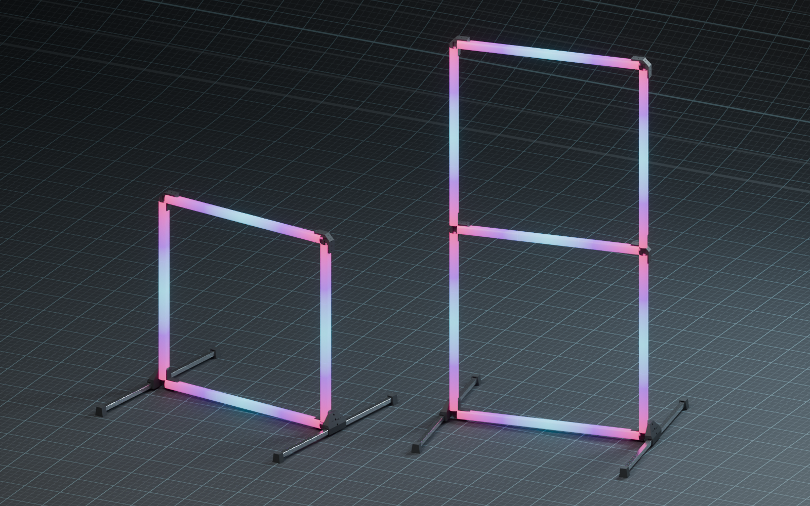
| Towers | T piece TE1.3 + T cover CT1.1, shared middle rails | CAD only; double and triple tower in the explorer |
| LEDs | WS2812B strip, 60 LEDs/m | Soldered across the corners; no plug connectors for now |
Not tested yet: a complete gate with lighting, the towers, and their stability. All images on this page are CAD views.
One project, several connected pieces
The gate combines a mechanical frame, lighting and a wireless control concept. A USB gateway sends short GateLink radio commands to a gate node; the node runs WLED and produces LED effects locally. Race-event data could feed the gateway through a future bridge, and the same broadcasts could drive small race receivers for pilots (why LoRa and what travels over the air).
GateLink and wireless nodes · GateLink simulator · Project log · Cost estimate · Earlier concepts
Open the interactive GateLink simulator: choose Offline to explore the virtual gate, lighting and packet flow. LED effects and wiring are approximations, not a physical LED test.
Using the explorer
- Project: click any part in the model. The details panel shows what it is, its revision, material, PETG mass, estimated print time, price and sourcing links, firmware notes for the microcontrollers, and which parts it connects to. The breadcrumb leads to the parent assemblies (light rail, foot, controller box); Ghost others, Isolate and Exploded view put one assembly in focus. The product structure, a bill of materials with CSV download and links to the GateLink software sit in the side panel.
- Assembly guide: nine steps; the camera moves to each joint. Start assembly fresh jumps back to step 1. M3 screws and inserts are optional.
- Individual parts: each revision on its own, with its counterpart and the original STL/STEP print files.
The controller box GC0.1 is a placeholder, not a designed part. It sits behind the lower rail at the lower-left corner and stays below the diffuser, so it does not reach into the gate opening, and it is held by two M3 screws in the two free lower-face pilots of the corner, which stays unchanged. Inside: Module 1 Seeed XIAO ESP32-S3 (WLED with the GateLink usermod, drives the LEDs), Module 2 Seeed XIAO ESP32-C5 (lap tracker), Module 3 Seeed Wio-SX1262 LoRa (GateLink radio) and a placeholder battery pack. Prices were checked on 5 November 2026; mass is the solid CAD volume and print times come from PrusaSlicer runs on the released STL files, calibrated to OrcaSlicer results of printed parts (about 28 h for a single gate, most of it the twelve diffuser pieces). The GateLink code repositories are private for now. Planned: the GateLink simulator will also flash real gate controllers.
The default build shows the newest corner CR6.7 (CR6.5 catch plus an inner fill with a cover pilot) and foot bracket FB6.3: a clip bump with a 60° retention flank catches in a pocket in each corner tail, with zero vertical play. This pair is not printed yet; the 60° catch was tested only on small test pieces. The predecessor pair CR6.4 + FB6.2 (55° catch) was printed and fits, but holds more softly; it is selectable under Build version as the printed pair. The DF6 diffusers are not fit-tested yet. Older builds, including CR5.1 + FB5.2, the FB3.1 reference and the FB4.1 latch experiment, stay selectable. The frame tube length is a placeholder; the legs are 330 mm.
Double and triple gates. Two kinds of multi-gate builds are selectable, both on 330 mm feet:
- Fixed towers (double, triple): the squares share their middle rails. At each inner junction a T piece TE1.3 replaces the two top corners of the square below. TE1.3 is the corner mirrored at the rail axis, with 45° inner fills and the same dovetail, catch pockets and insert positions as the corner, so single-gate add-ons fit. One print serves both sides. A T cover CT1.1 matches the corner cover CC2.3 and is fixed with two countersunk M3 screws. The tower is assembled once and stays together. Not printed yet.
- Stacked gates (double, triple): independent single gates stand corner on corner. There is no connector part at that junction, so the stacking is illustrative only.
Stability of the towers (about 1.3 m and 1.9 m tall) is not verified.
Design and documentation prepared with substantial OpenAI Codex and Claude assistance under the project owner’s direction.
Local review draft: diffuser and FB5.2 images
Article changes
- — The project explorer now opens directly at the top of the page with its assembly animation; the render moved below. Print times come from PrusaSlicer, the legs are 330 mm, and the opened controller box labels its modules.
- — The assembly explorer is now an interactive project documentation. Every part can be clicked for material, PETG mass, print time, price, sourcing links, firmware and how it connects to other parts, with a product structure, bill of materials, focus and exploded views. A placeholder GateLink controller box with the XIAO ESP32-S3, XIAO ESP32-C5 and Wio-SX1262 sits at the lower-left corner. "Start assembly fresh" replaces "Take it apart".
- — The assembly and part explorers now show corner CR6.5 and foot bracket FB6.3 with the 60° zero-play snap catch, plus the printed CR6.4 and FB6.2 pair. Test coupons are no longer listed in the part explorer.
- — The assembly and part explorers now show the newest CAD revisions, corner CR5.1, foot bracket FB5.2 with a snap clip and the DF6 diffuser rail set, with their STL/STEP print files.
- — Restructured around the current square-tube design with project status, interactive assembly guide and a 20-gate cost estimate; earlier U and V concepts moved to the archive.