Tinywhoop LED Gate
Published: 02 Oct 2026
A modular racing gate with aluminum rails, 3D-printed connectors and segmented diffusers. The aim is a stable frame that is easy to assemble and visible from several directions.
Project status · 4 October 2026. U-profile prototypes have been tested. The V-profile and square-tube versions are untested concepts. All images below are CAD views, not photographs or proof of physical performance.
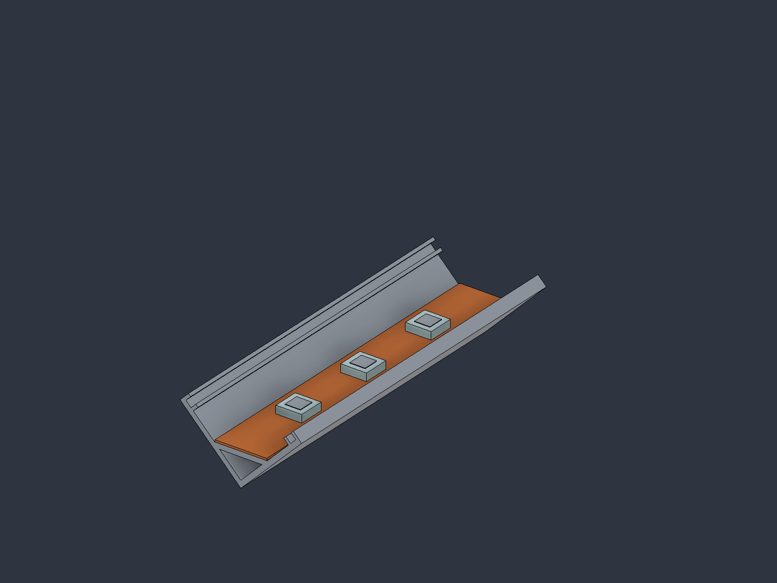
Planned lighting: WS2812 strips with 60 LEDs per meter, giving a 16.67 mm center spacing. The CAD views show 5 × 5 mm 5050 housings; 10 mm PCB width, 0.4 mm PCB thickness and roughly 1.6 mm housing height are illustrative until the actual strip is selected. WS2812 family, Worldsemi.
| Concept | Status | Main finding / next question |
|---|---|---|
| U-profile LED rail | Tested; not pursued further | Too easy to twist, including the inward-facing variant |
| V-profile LED rail | CAD concept; physical test pending | Test stiffness, retention and diffuser visibility from behind |
| 15 × 15 × 1 mm square tube | Preferred next experiment | Test the closed-section frame, then develop connectors and a diffuser |
1 · U-profile prototypes — tested, insufficient stiffness
The original prototype used shallow U-profile LED rails with the LEDs facing the incoming drone. During the project owner's physical assembly tests, the rails twisted easily and the gate did not stand sufficiently rigidly.
A second prototype rotated the U profile by 90°, placing the LEDs toward the gate opening. The owner reported some improvement in the assembled frame, but it was still too flexible. Rotation changes the bending orientation; it does not increase the rail's intrinsic torsional rigidity.
U-shaped profiles remain useful LED carriers, but this section was not satisfactory as the structural rail for this gate.
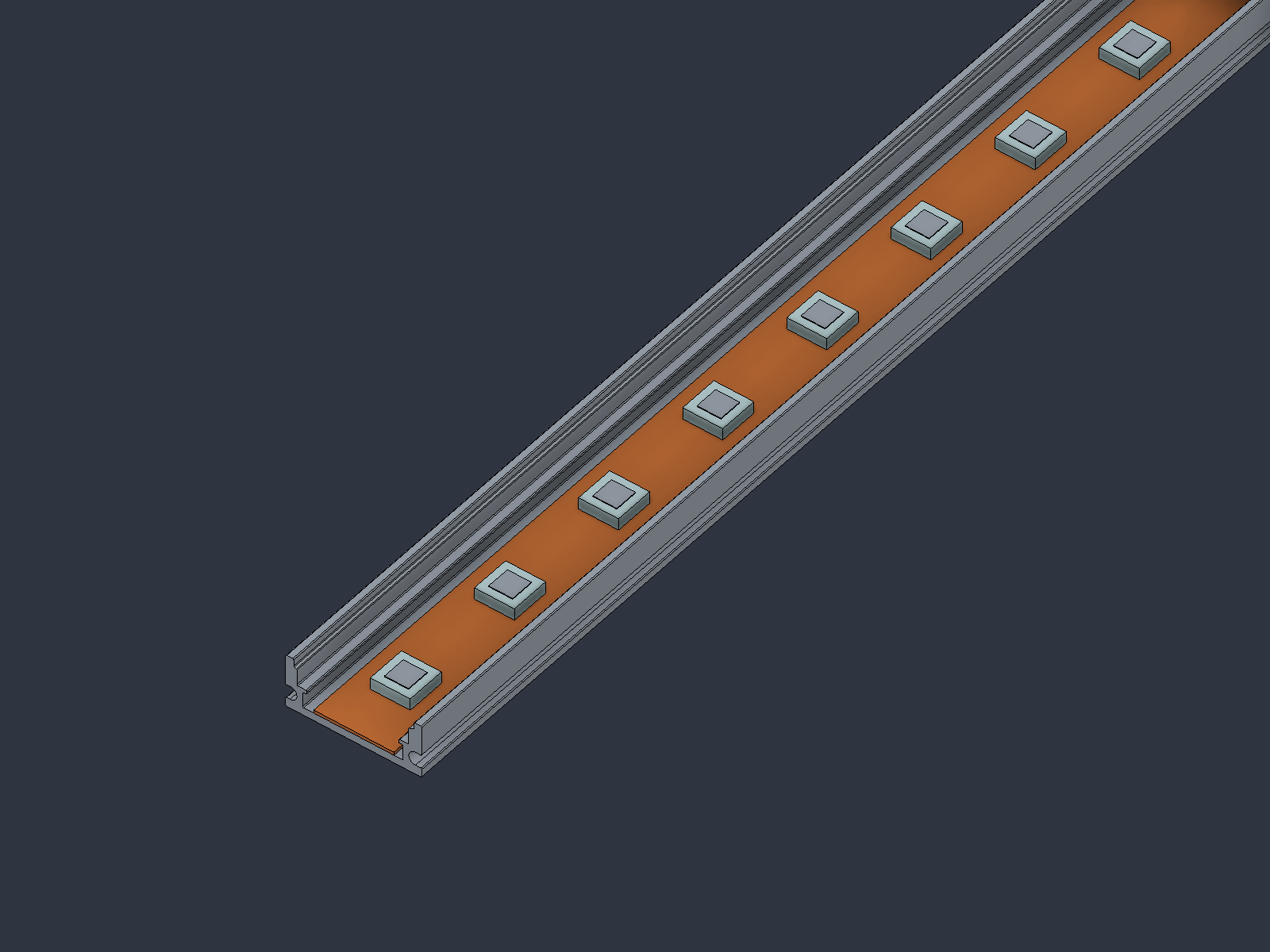
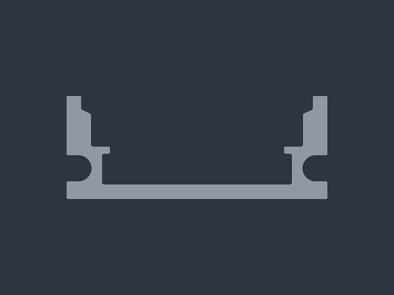
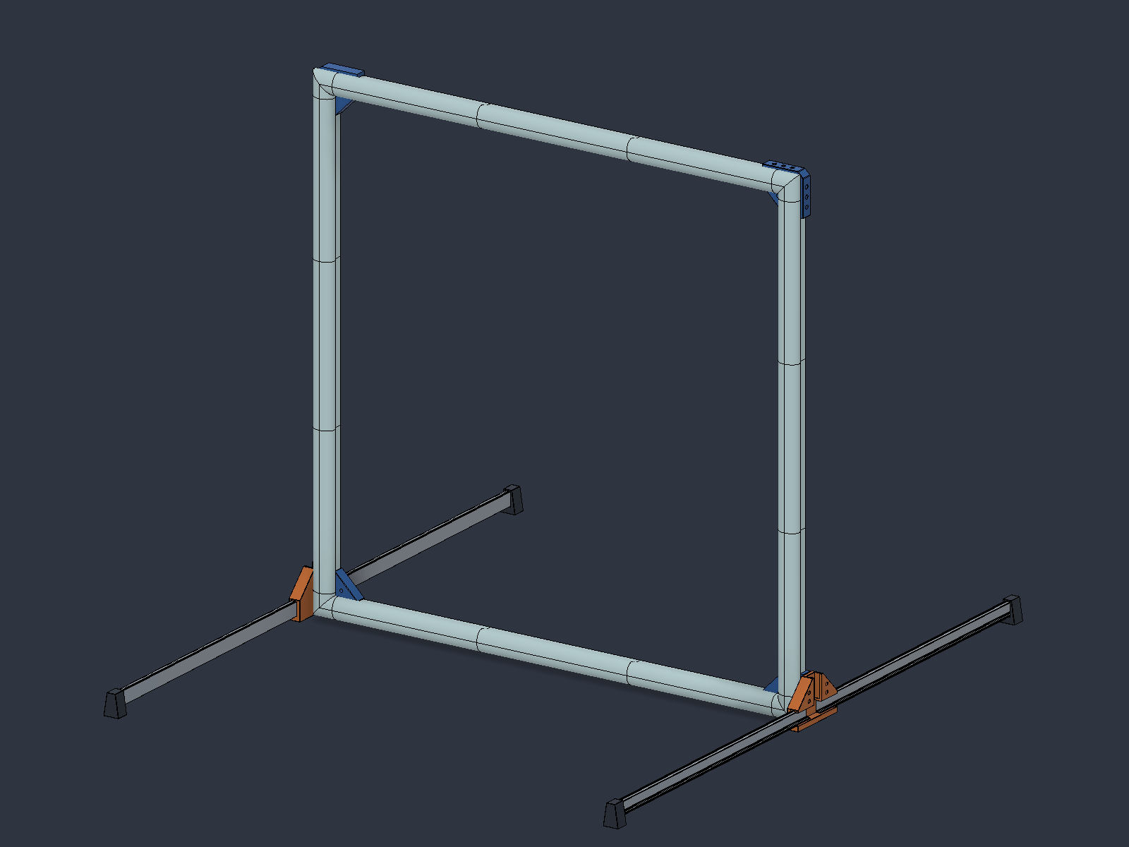
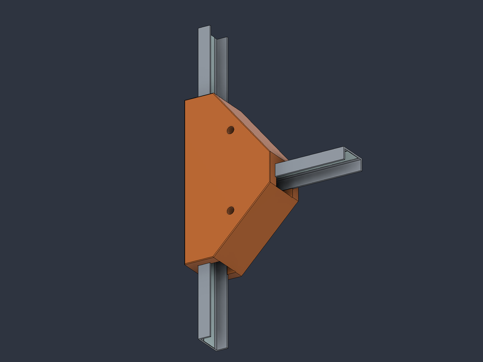
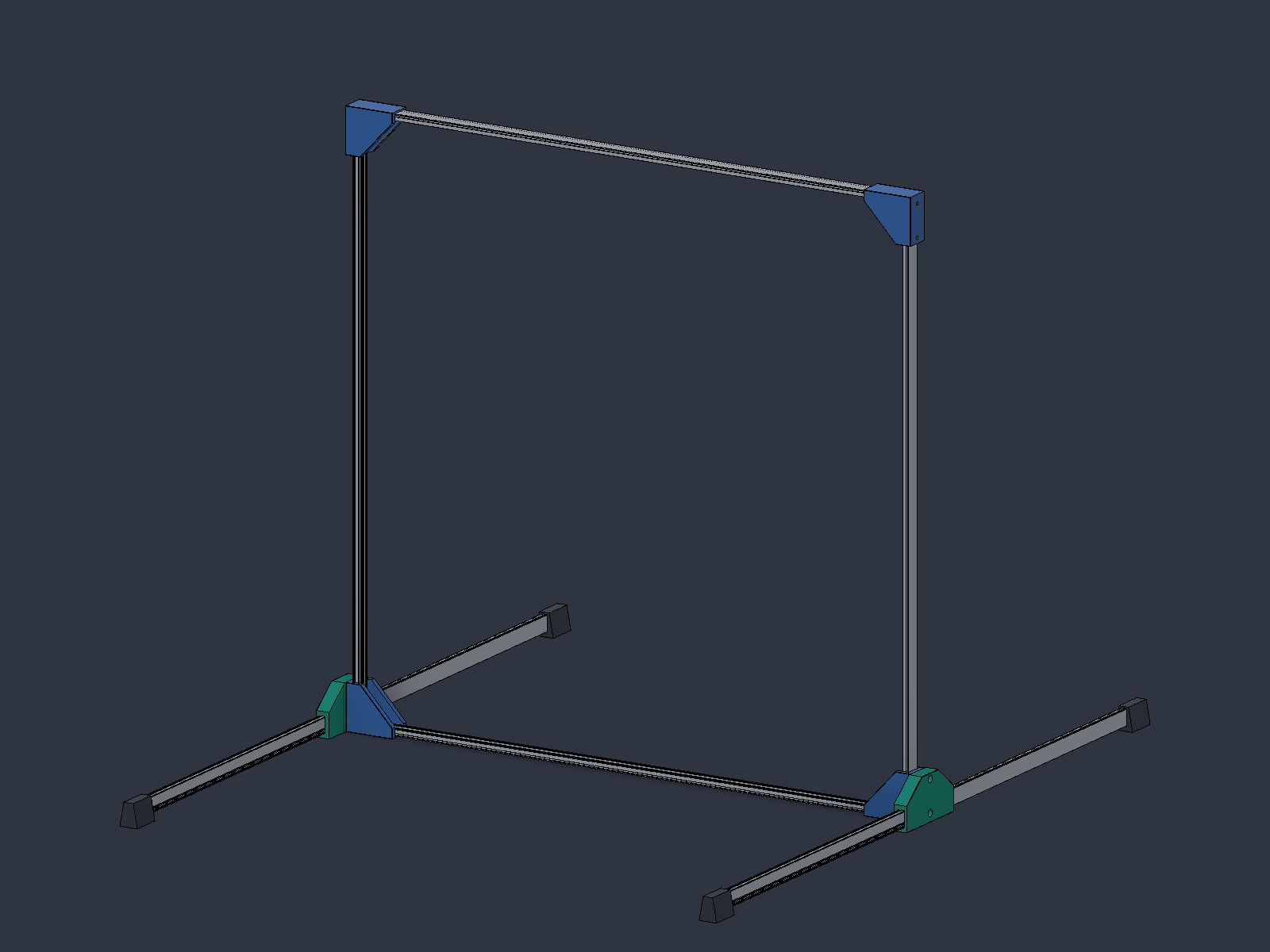
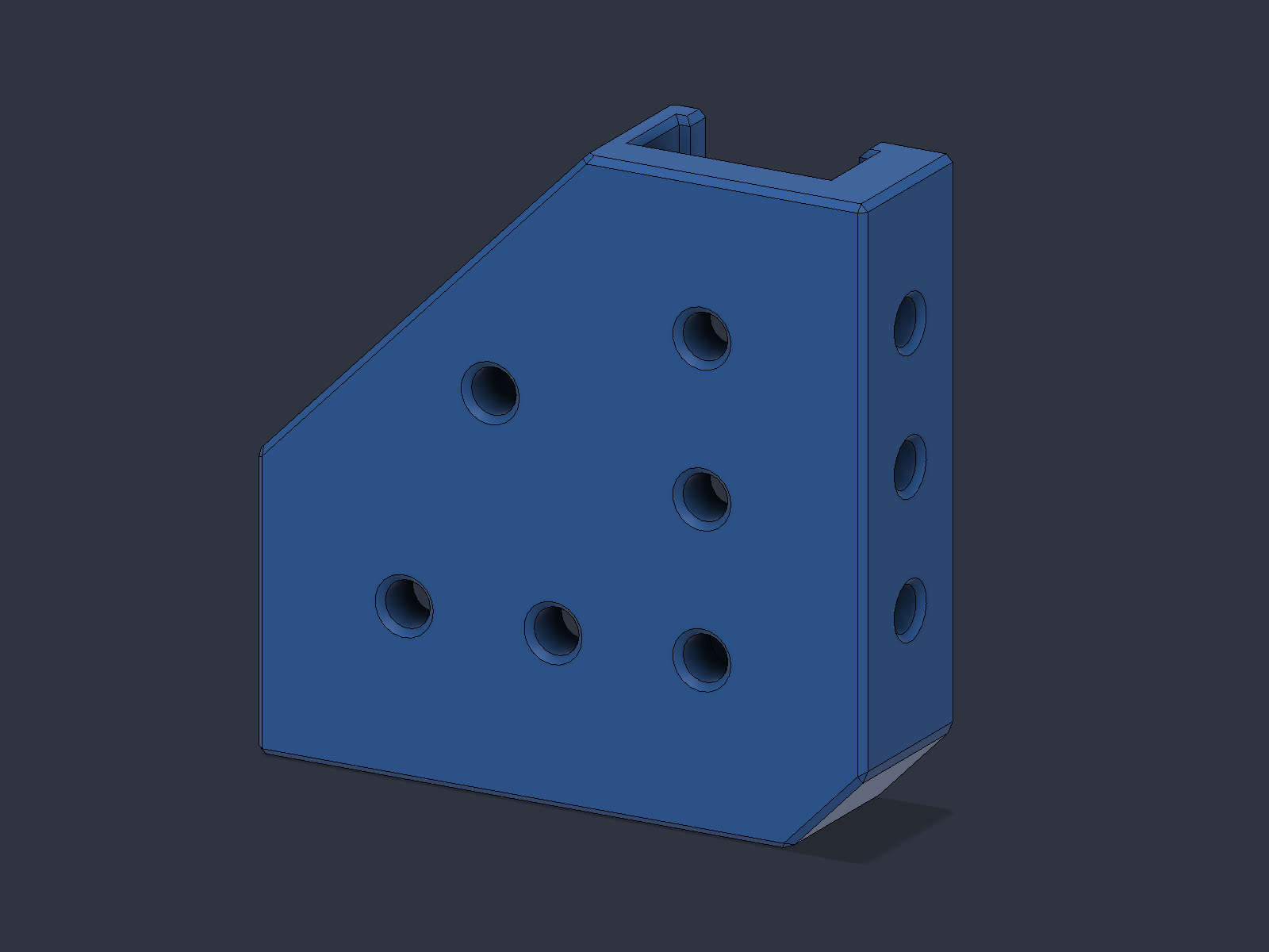
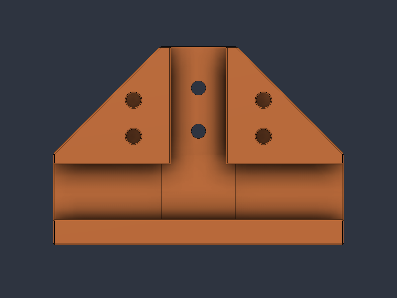
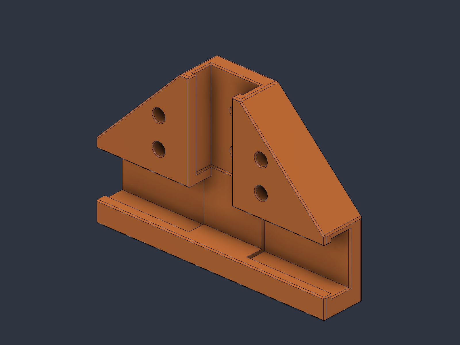
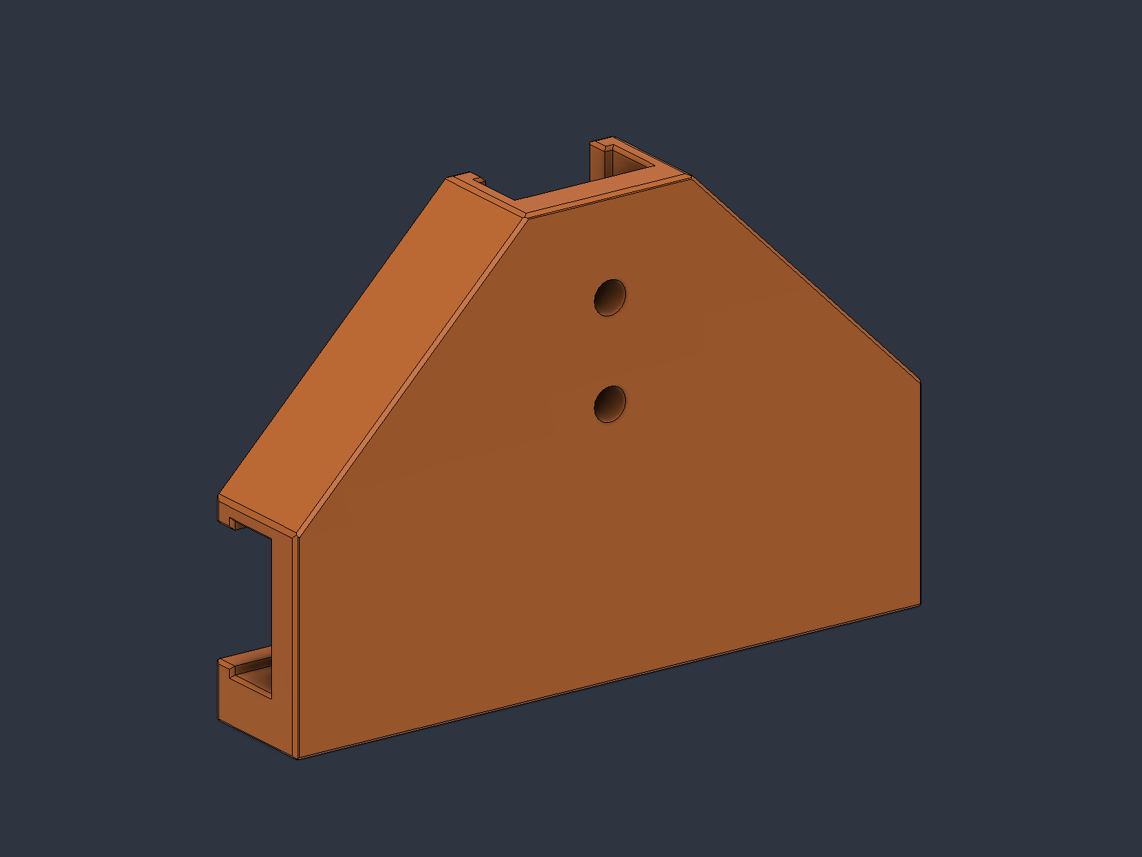
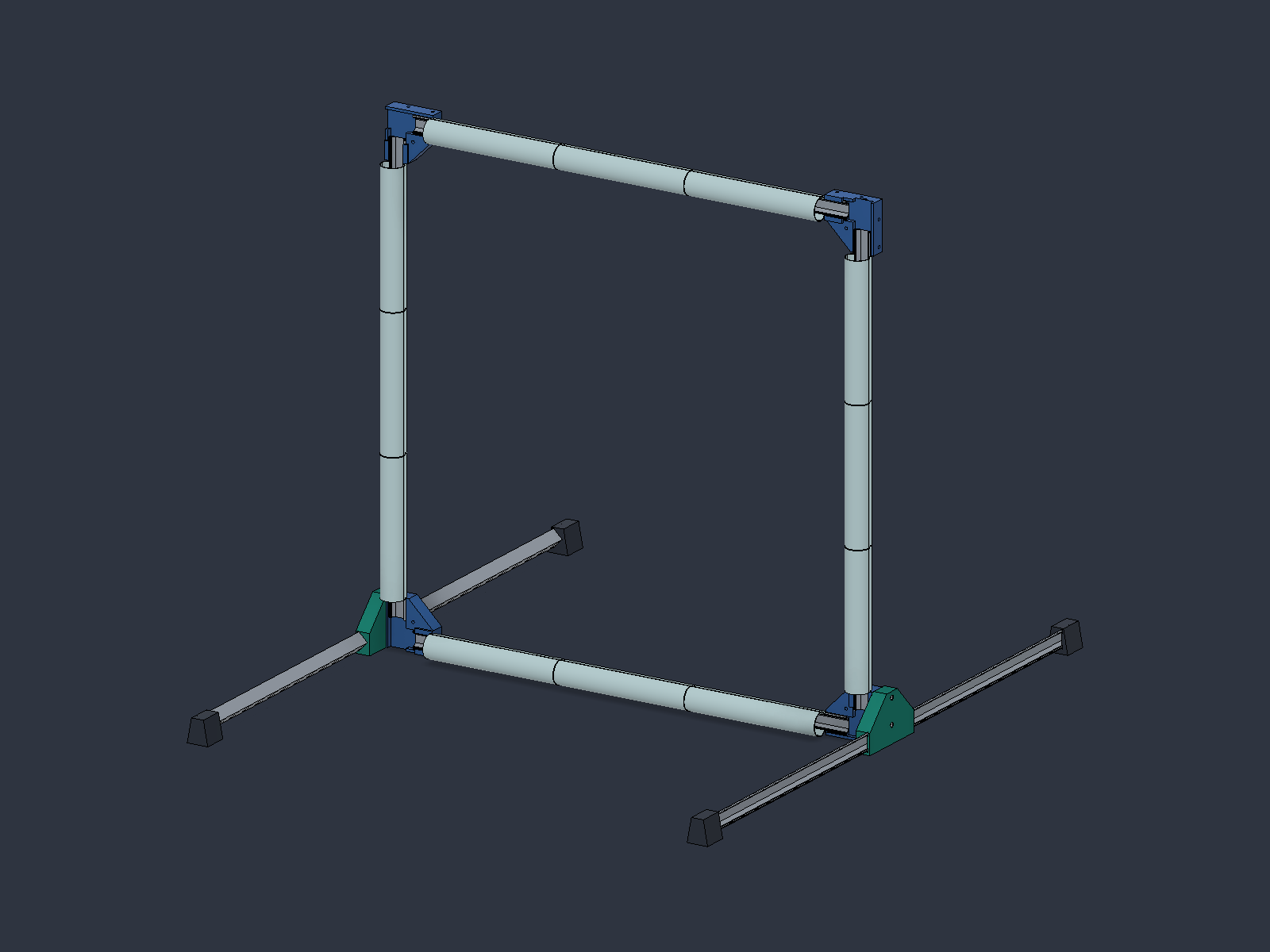
Original U-profile CAD assembly gallery · archive
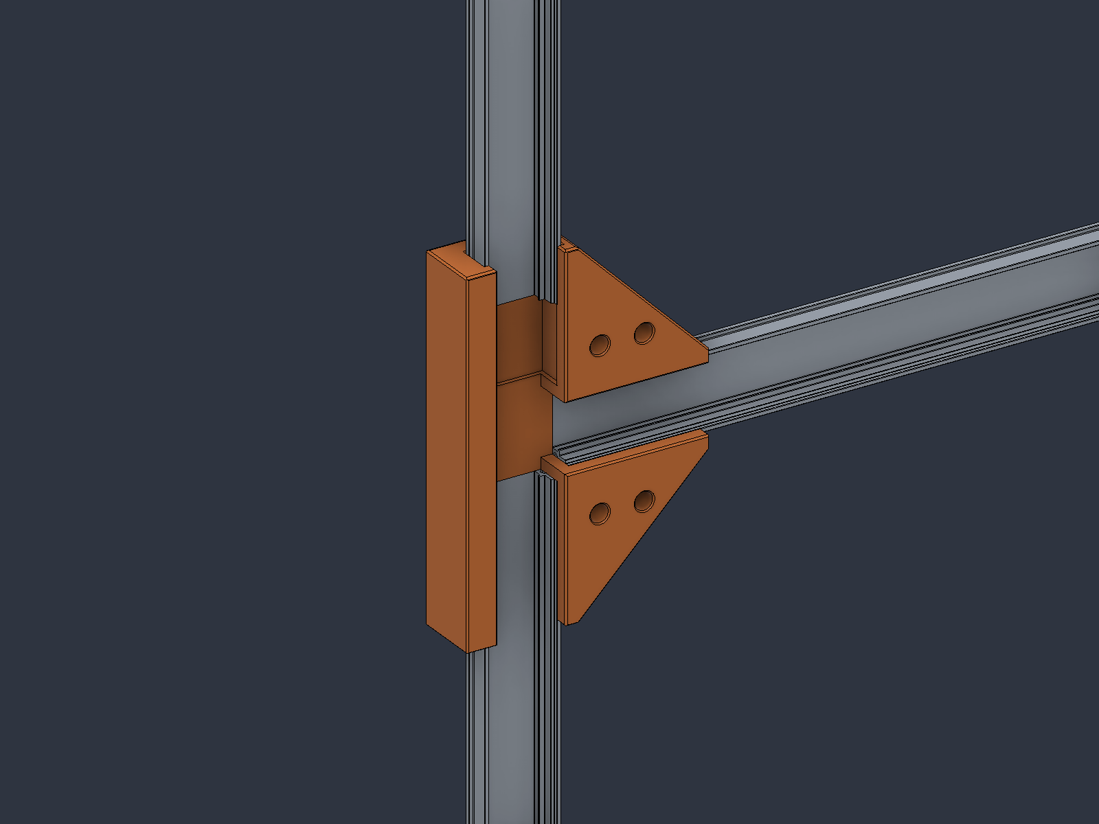
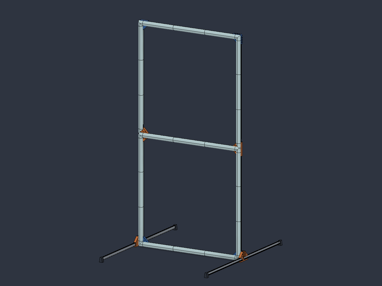
These images document the earlier connector and foot arrangement. They are retained as design history; they are not a current build recommendation.
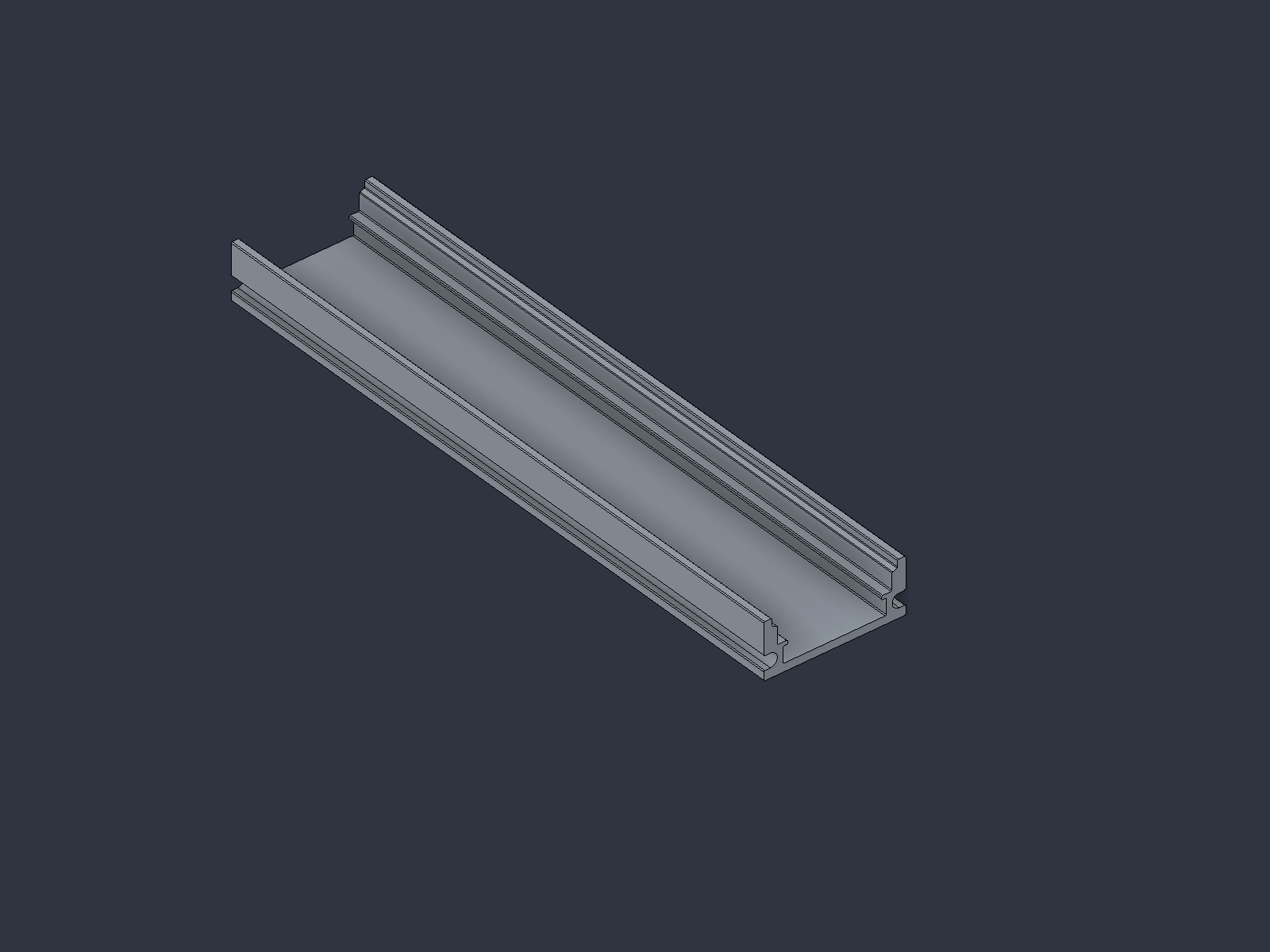
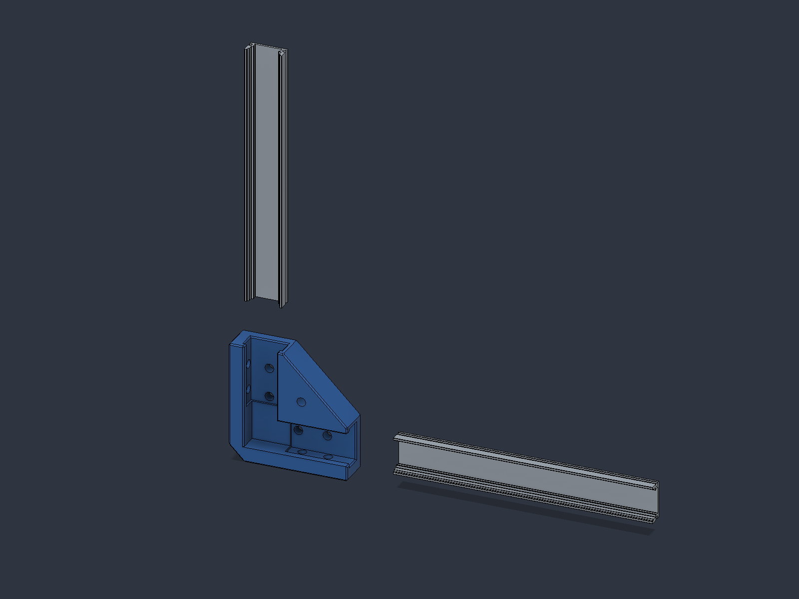
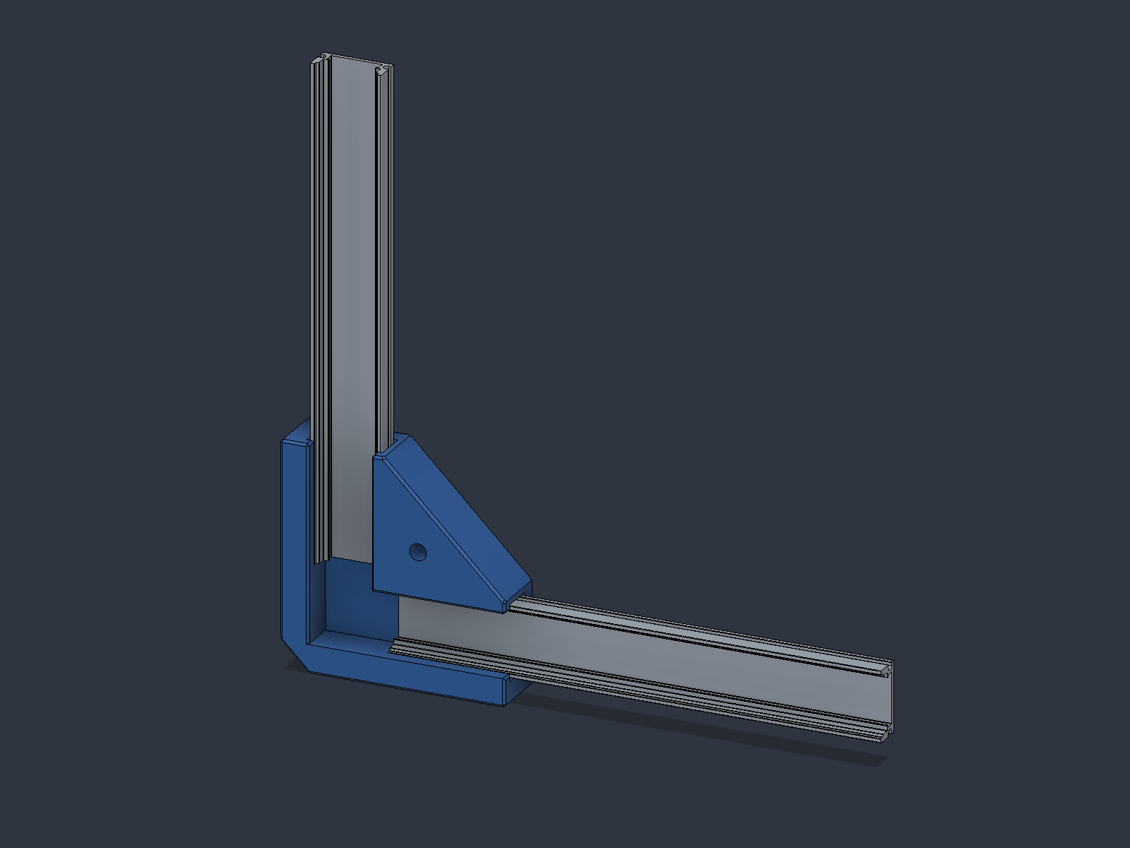
Aluminum profile
LED aluminum profile, based visually on the Jopassy U profile. The modeled contour is approximate.
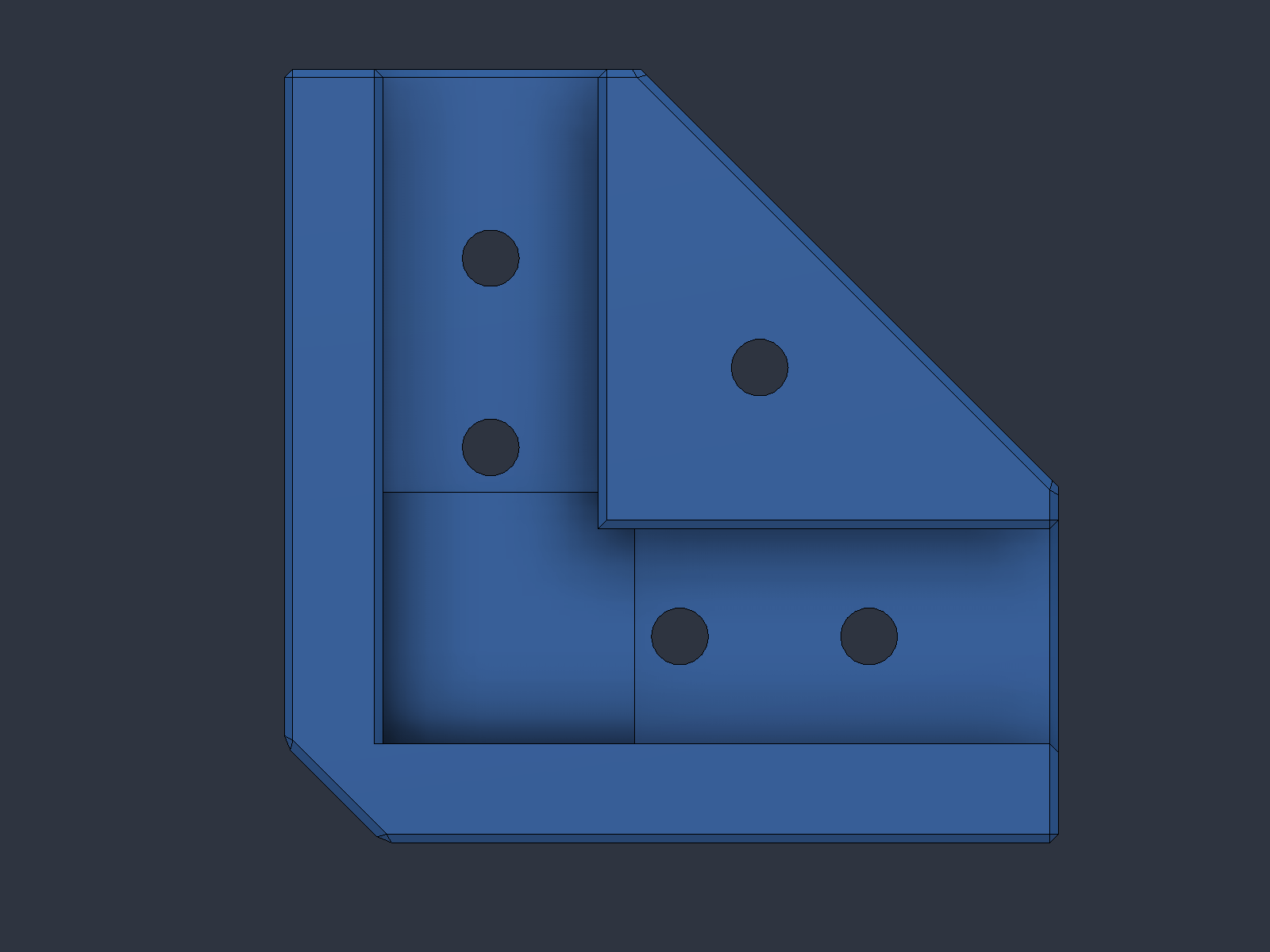
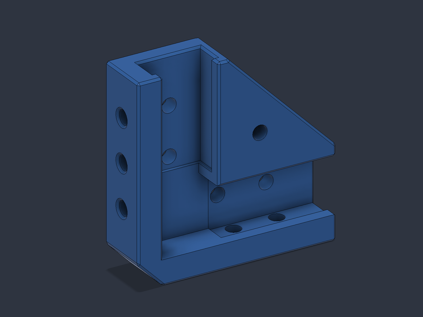
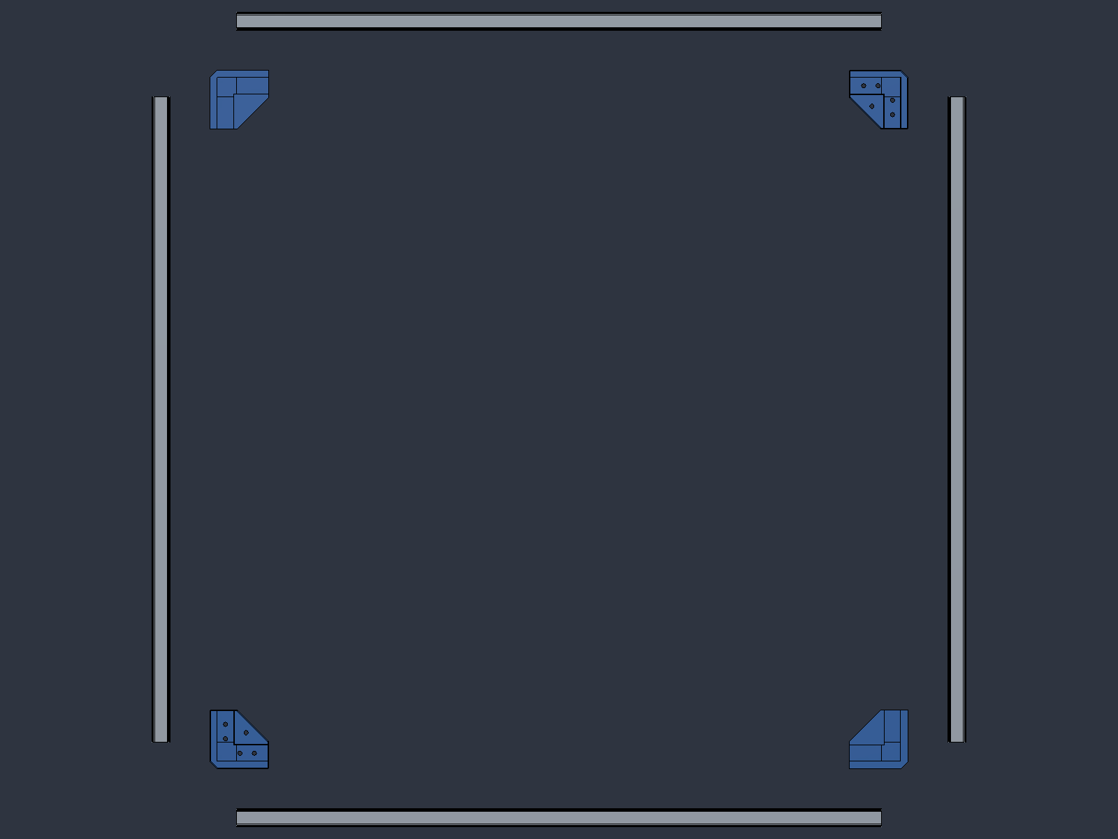
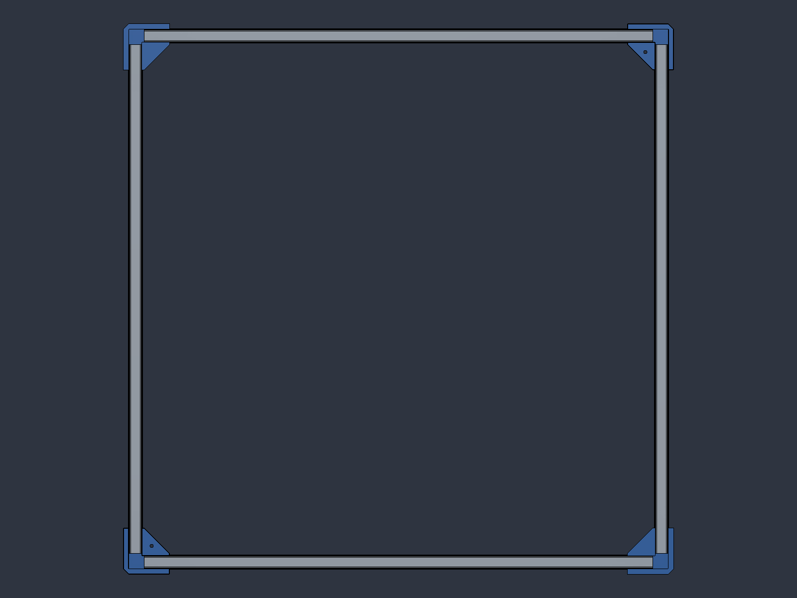
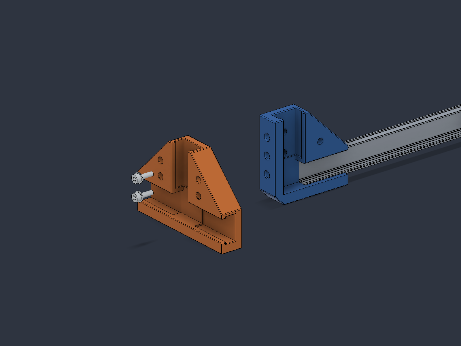
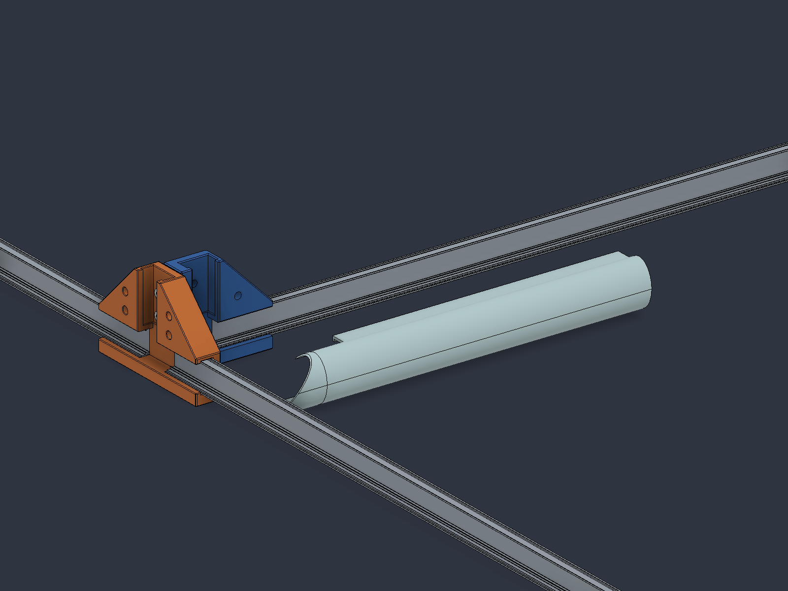
Printed 90° connector · blue
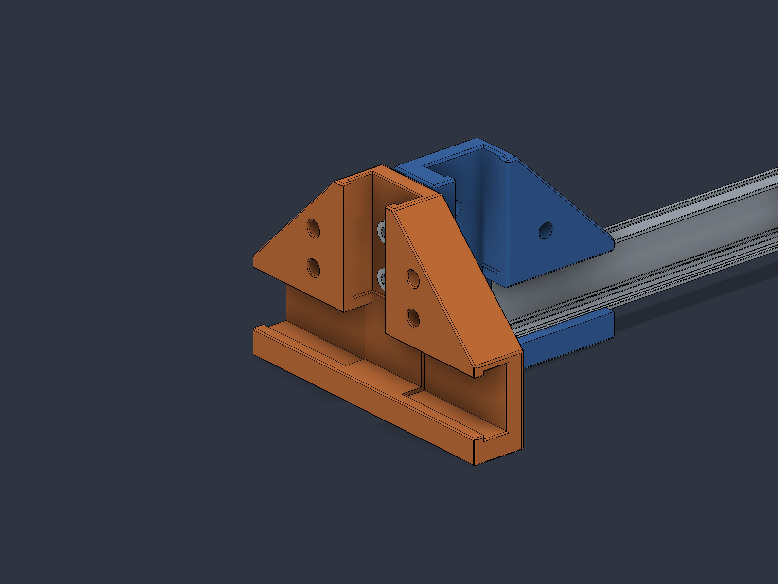
Printed T connector · orange
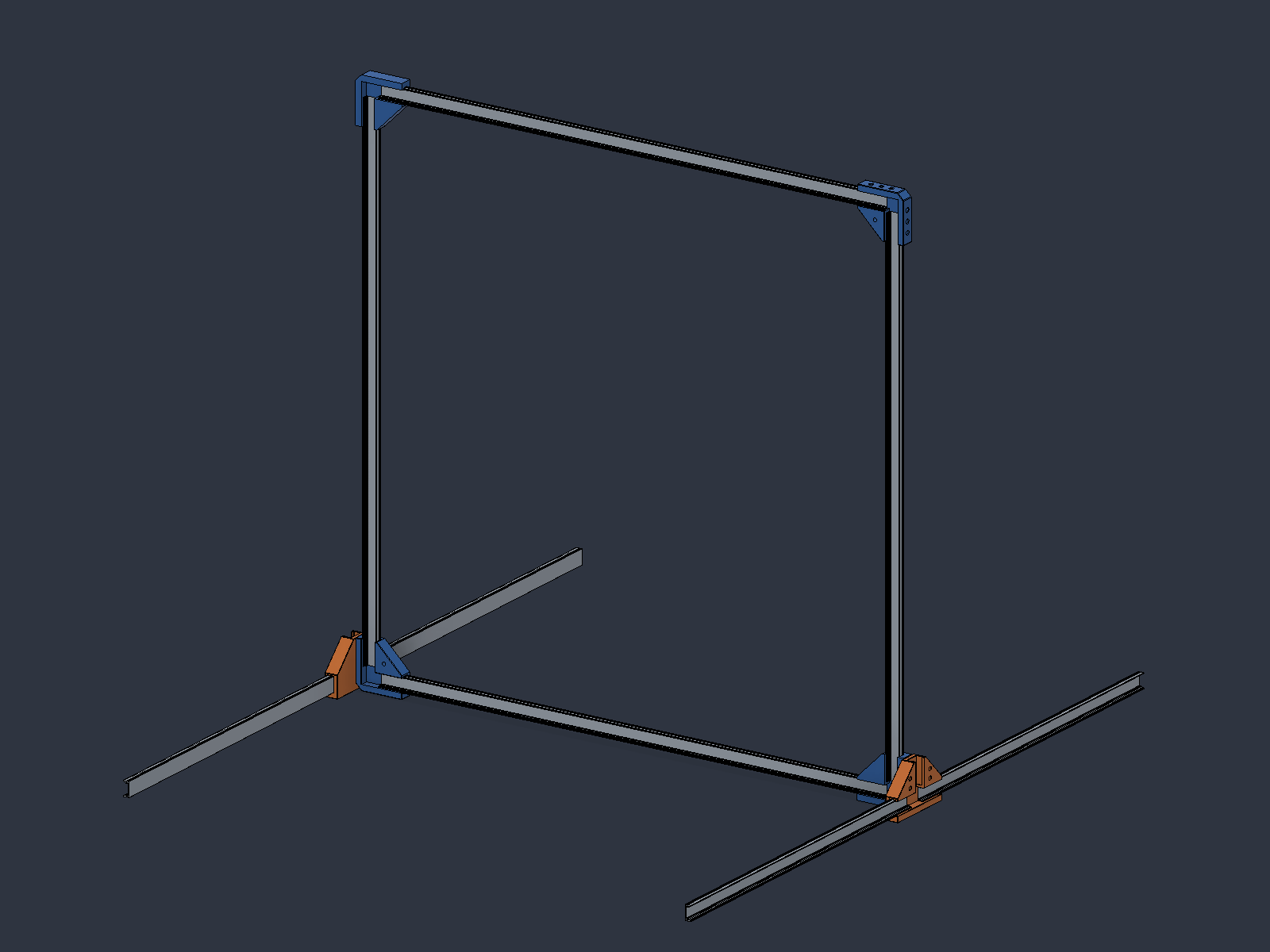
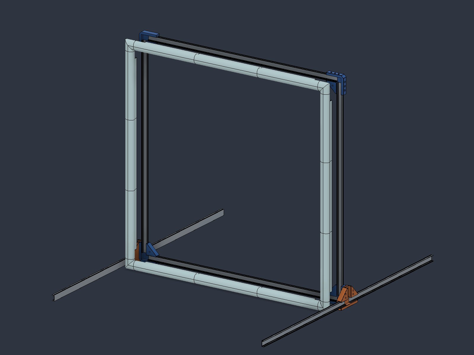
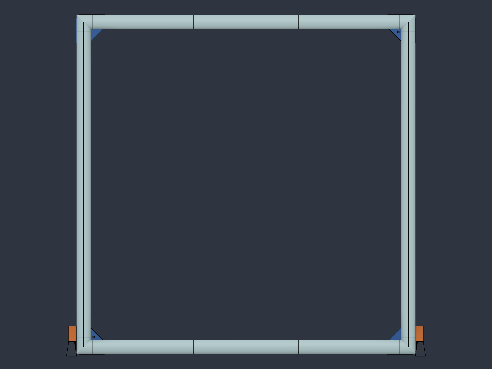
1 · Build the frame
2 · Add the feet
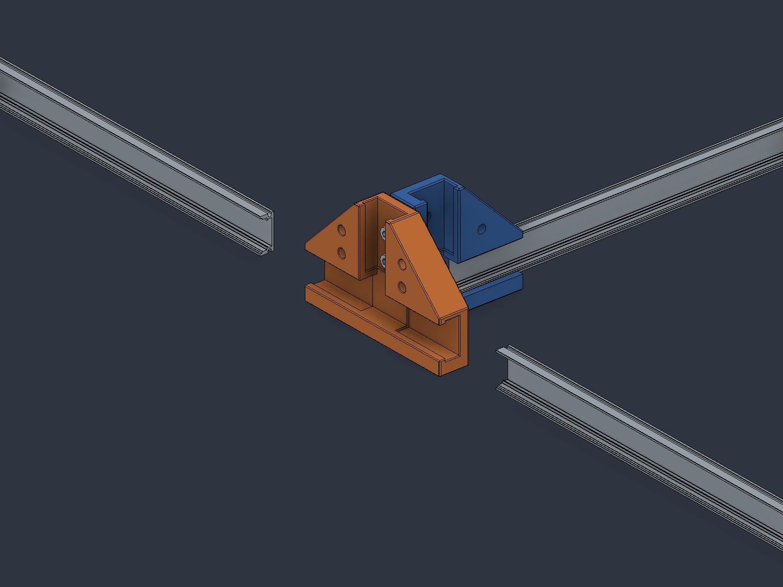
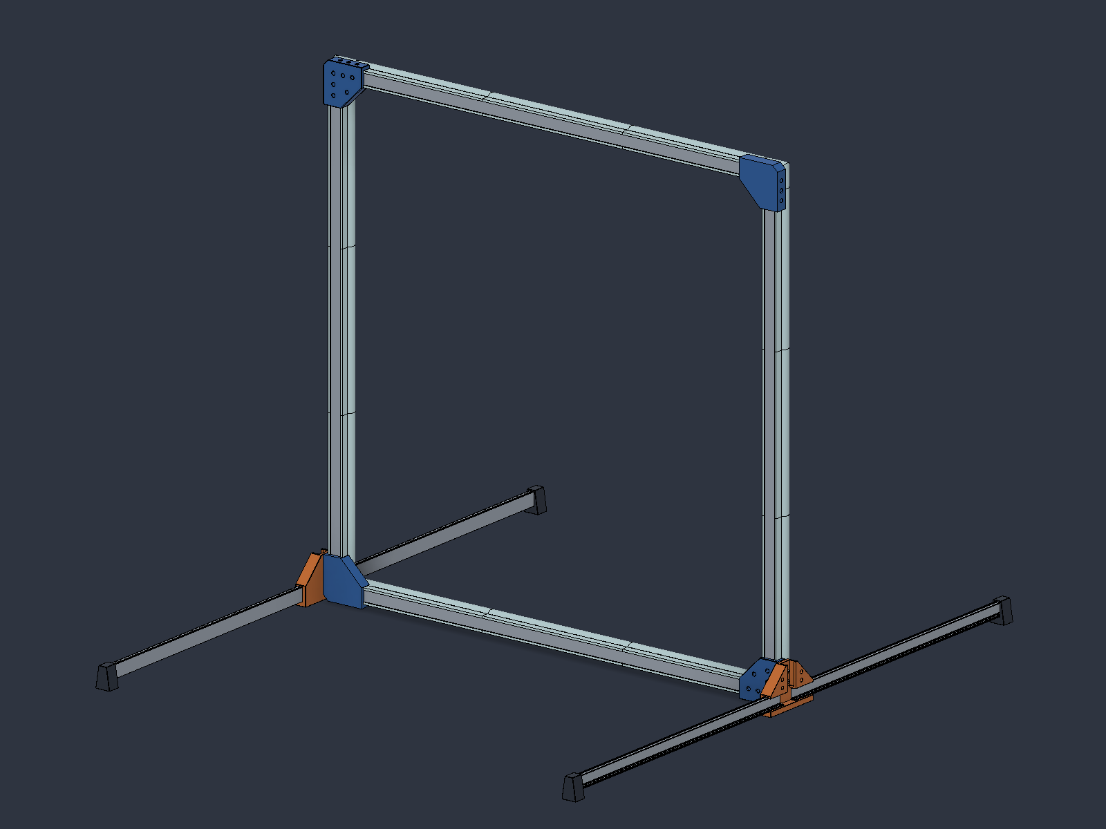
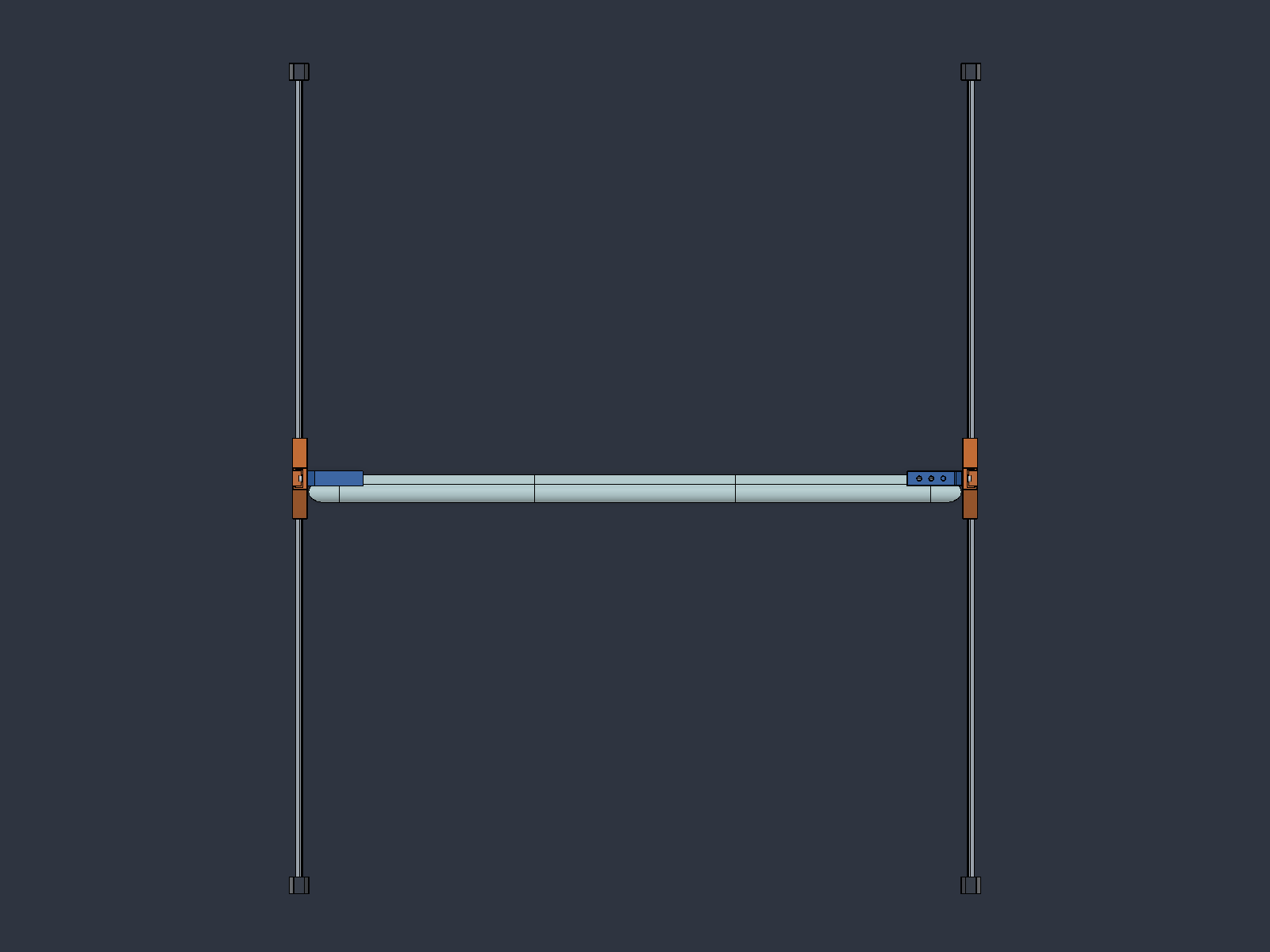
Each 1 m profile supplies a 600 mm gate bar and a roughly 400 mm foot offcut. The feet stand on edge for stiffness.
3 · Clip on the diffusers
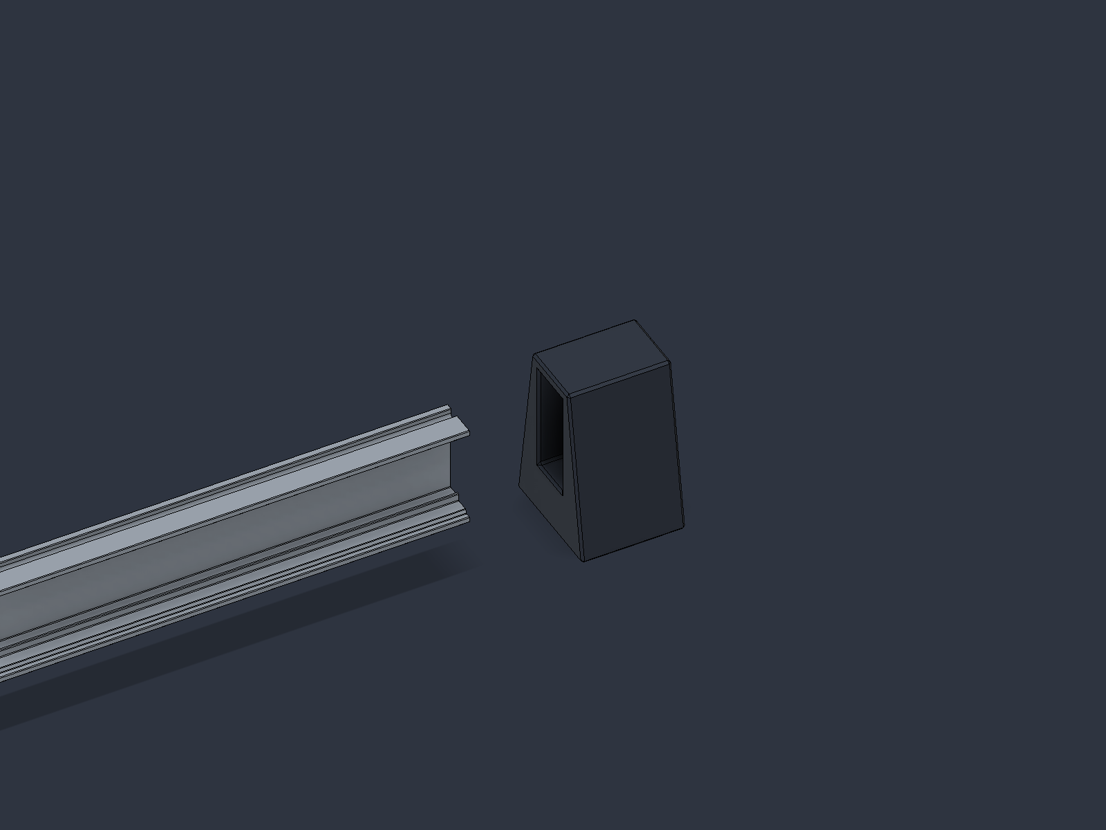
4 · Fit the foot caps
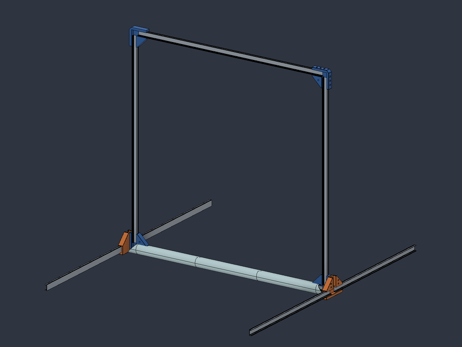
The complete gate
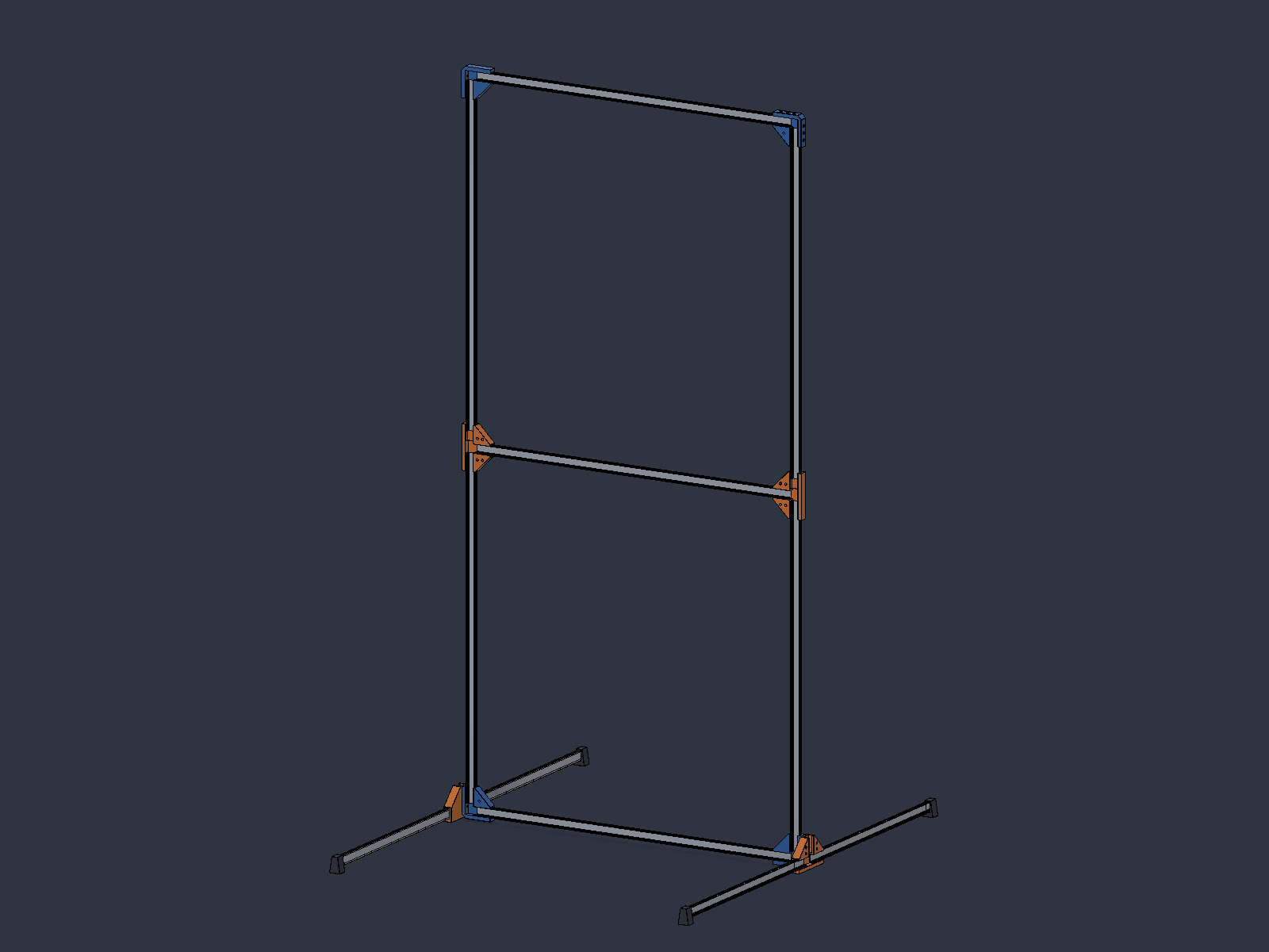
Extension · Double gate
The T connector also links two stacked frames. Diffuser details at the shared junction still need refinement.
2 · V-profile concept — awaiting a physical test
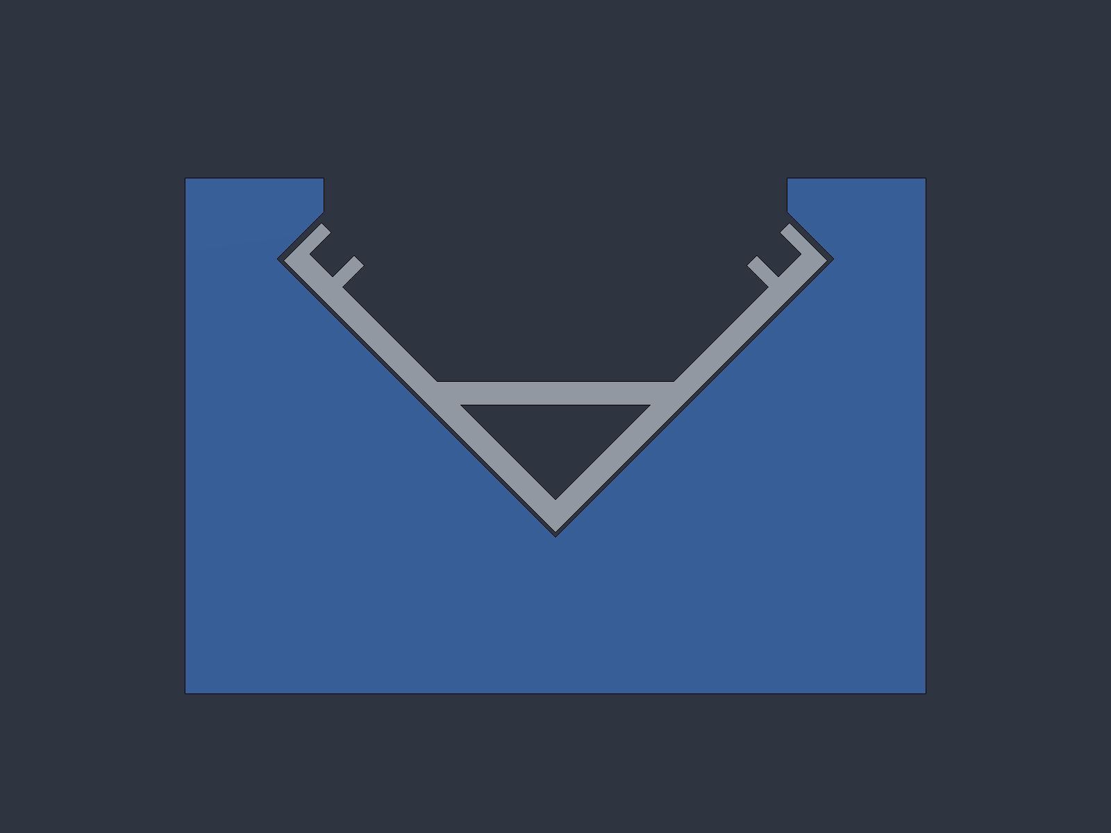
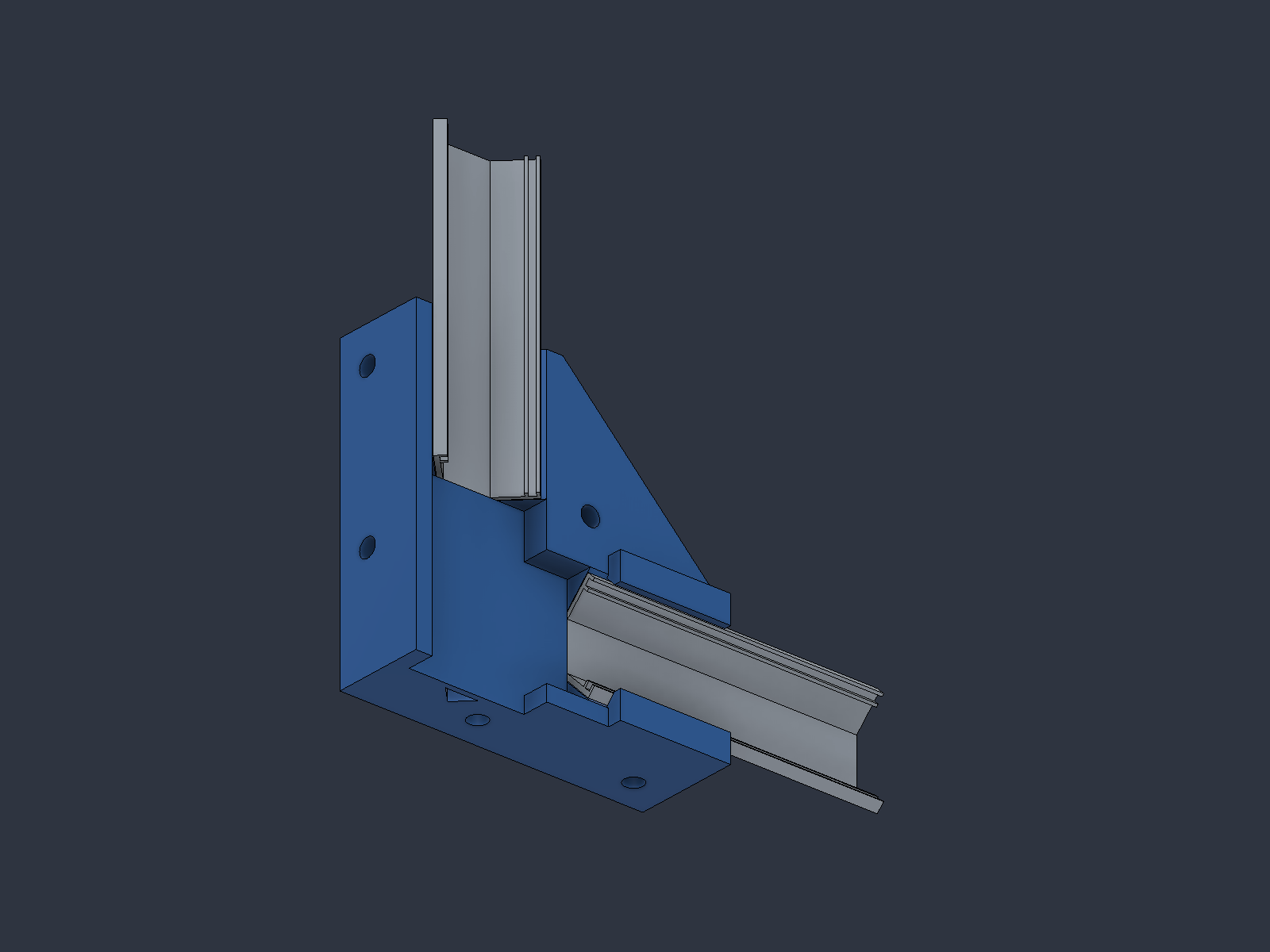
The Jopassy V-profile rail adds a closed triangular chamber below the LED bed. The hope is greater torsional rigidity than the shallow open U rail; the complete gate still needs a physical test.
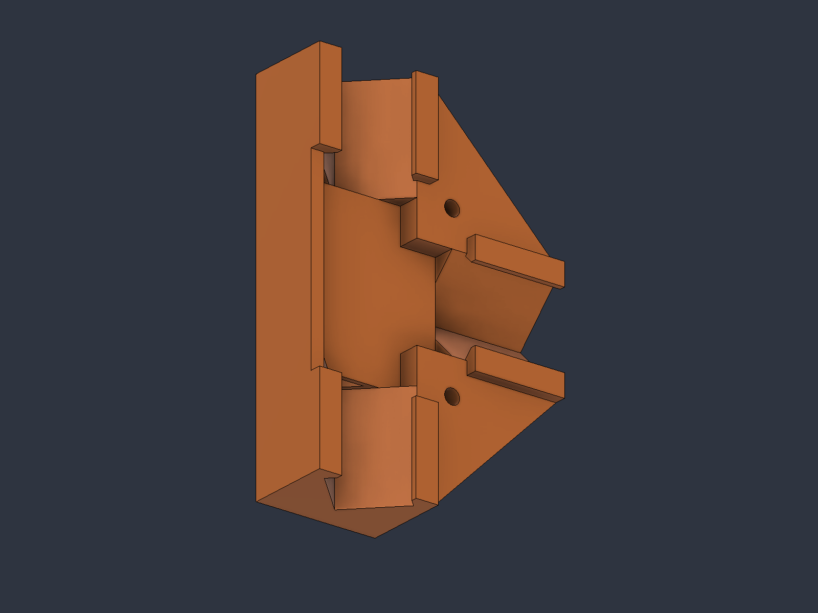
Printed 90° and T junctions use solid blocks with profile sockets, end stops and retaining lips. Their central LED support remains flat. The aluminum rim geometry is estimated from the listing's 16 mm flank dimension and is adjustable in Fusion; the dimensions are not yet verified against the delivered rail.
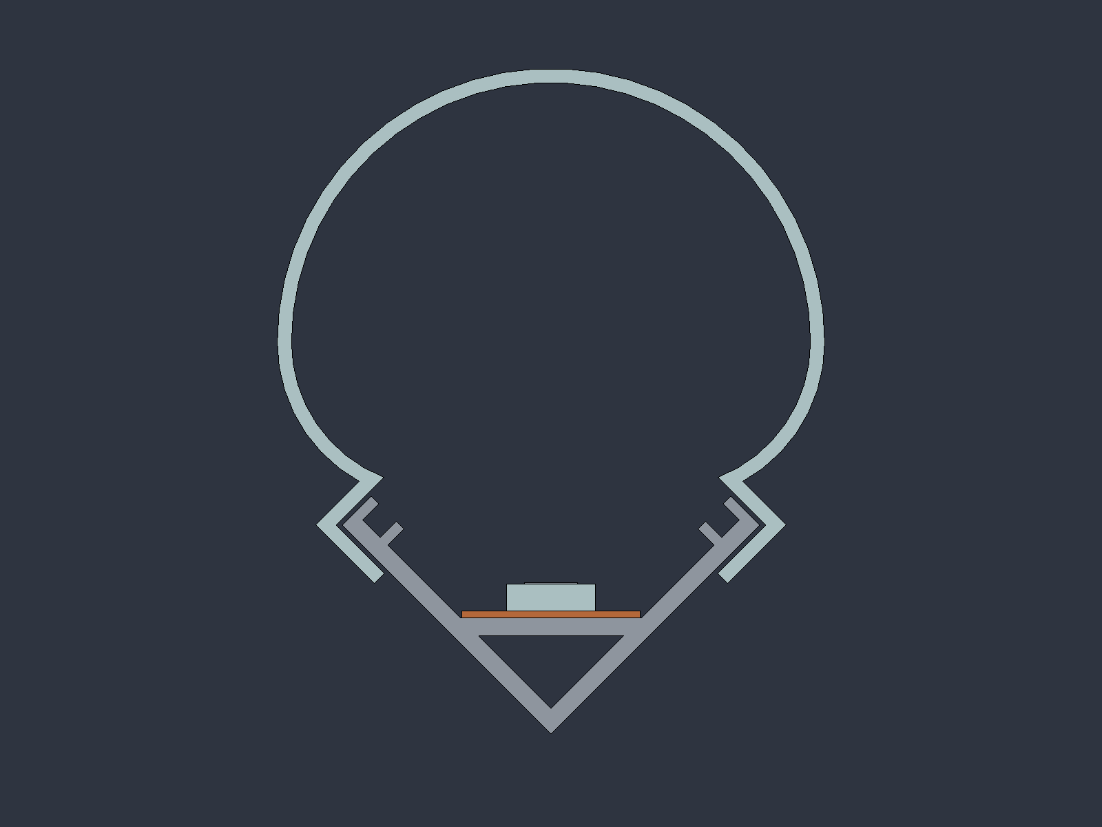
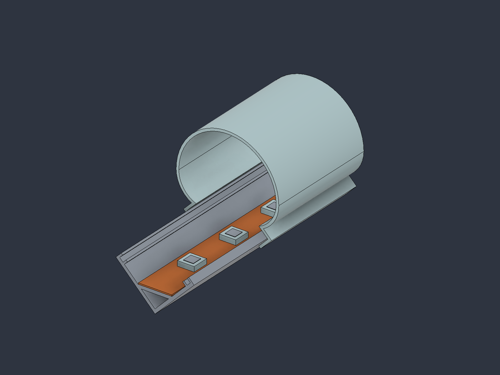
Main challenge: the diffuser. The wide metal section obscures the cover from behind. A printed cover must extend beyond the profile's silhouette to expose illuminated shoulders. The revised 0.8 mm cover wraps around the F-shaped rims and widens into a balloon chamber. Wrap depth, clearance and chamber dimensions are adjustable in Fusion; rear glow, printability and clip fit remain untested.
3 · Square-tube concept — preferred next experiment
Use a closed aluminum tube, 15 × 15 mm outside with a 1 mm wall, as the structural rail. The LED strip can adhere to a flat outer face; a separate printed diffuser provides the light shape.
A continuous closed section is expected to resist twisting much better than the shallow open U section at comparable dimensions. That makes it the preferred next experiment, rather than a validated final solution. Printed connector stiffness and clearance can still determine how rigid the assembled gate feels. Background: torsion of closed sections, MIT.
The starting layout remains four roughly 600 mm frame rails and four roughly 400 mm offcut feet from meter lengths, allowing for saw kerf.
Wraparound diffuser: the project owner's new section combines a 20 mm round light chamber with side arms and hooks behind the tube. The 0.8 mm optical wall is retained. It widens beyond the 15 mm tube to leave plastic visible around the metal silhouette; rear illumination remains to be tested.
The refinement adds 0.15 mm clearance per tube face and 0.4 mm entry ramps to a 180 mm module. Both rear hooks remain continuous: one 2D section is extruded along the whole module, with no intermediate steps for upright printing. Length, clearance and ramp depth are editable in Fusion; the section stays linked to the owner's original diffuser. These are starting values for a print trial, not proven fit tolerances.
Next test: print the separate 20 mm fit coupon and check installation force, retention and removal on the real tube. Then test a full module for rear glow and layer strength. Corner interfaces and the complete square-tube gate remain to be developed.
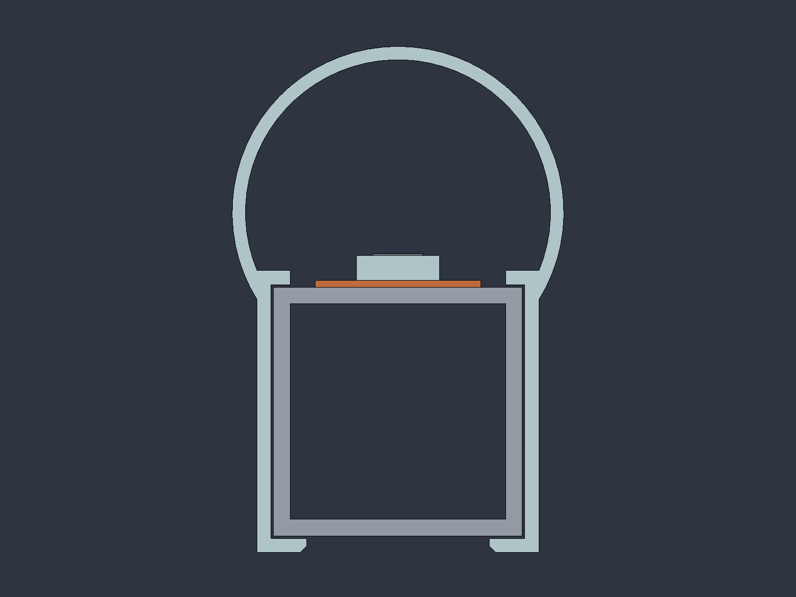
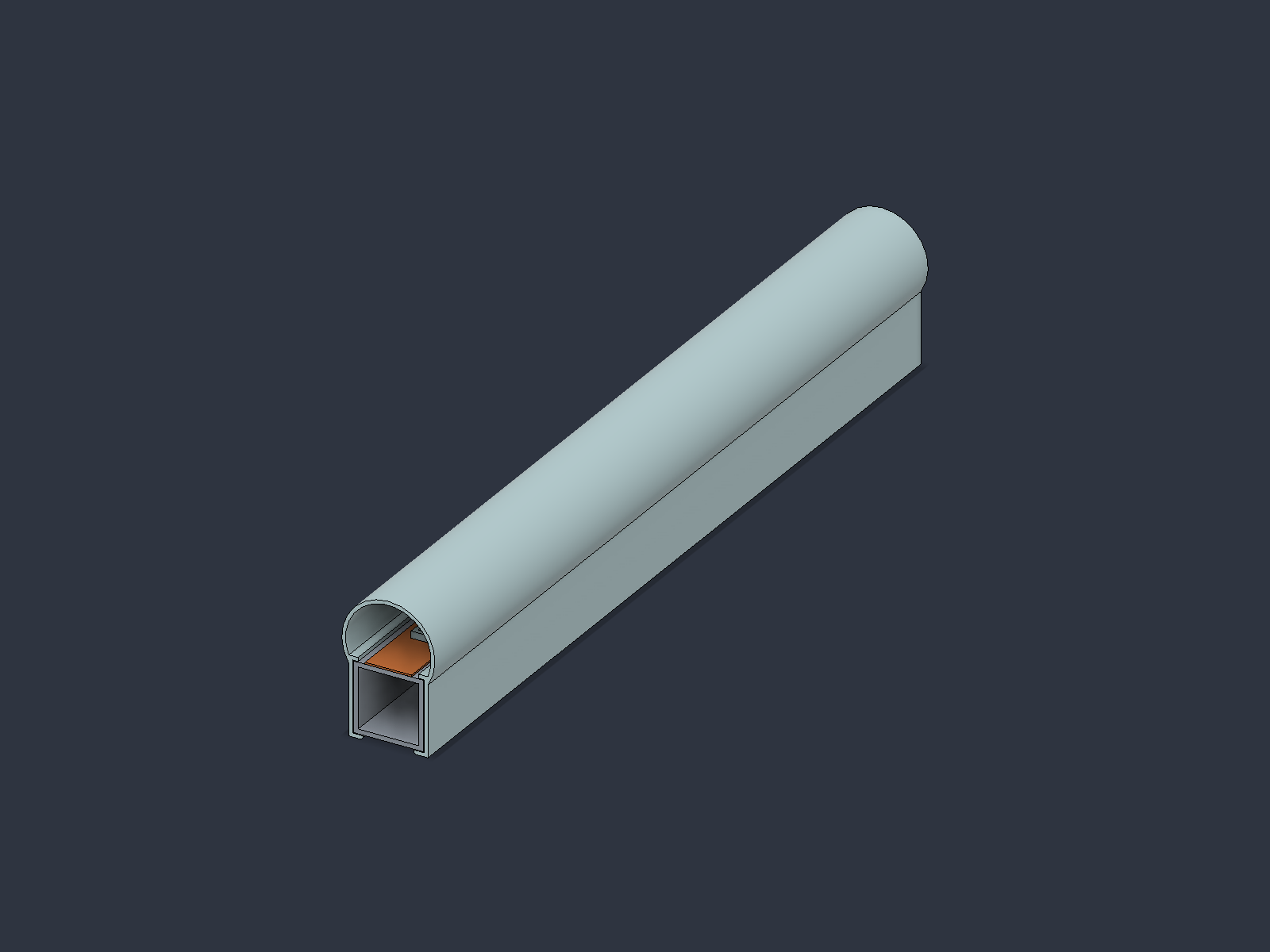
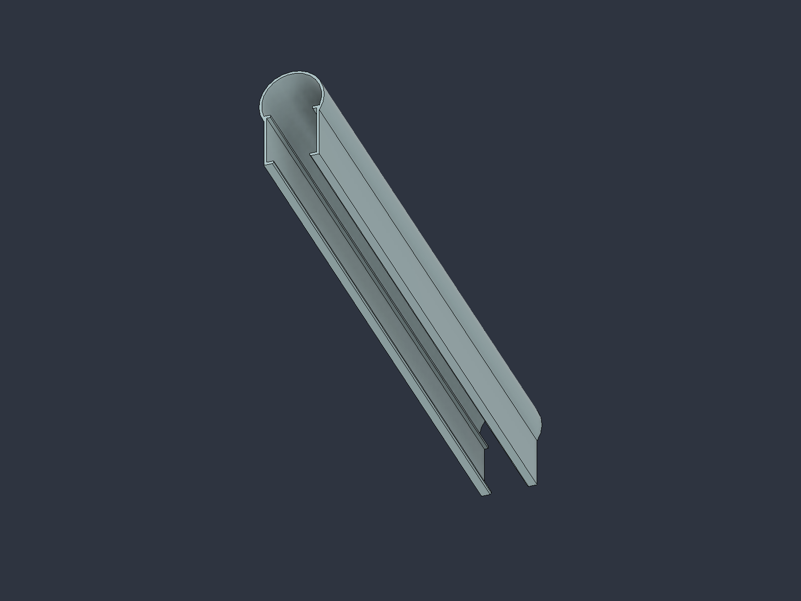
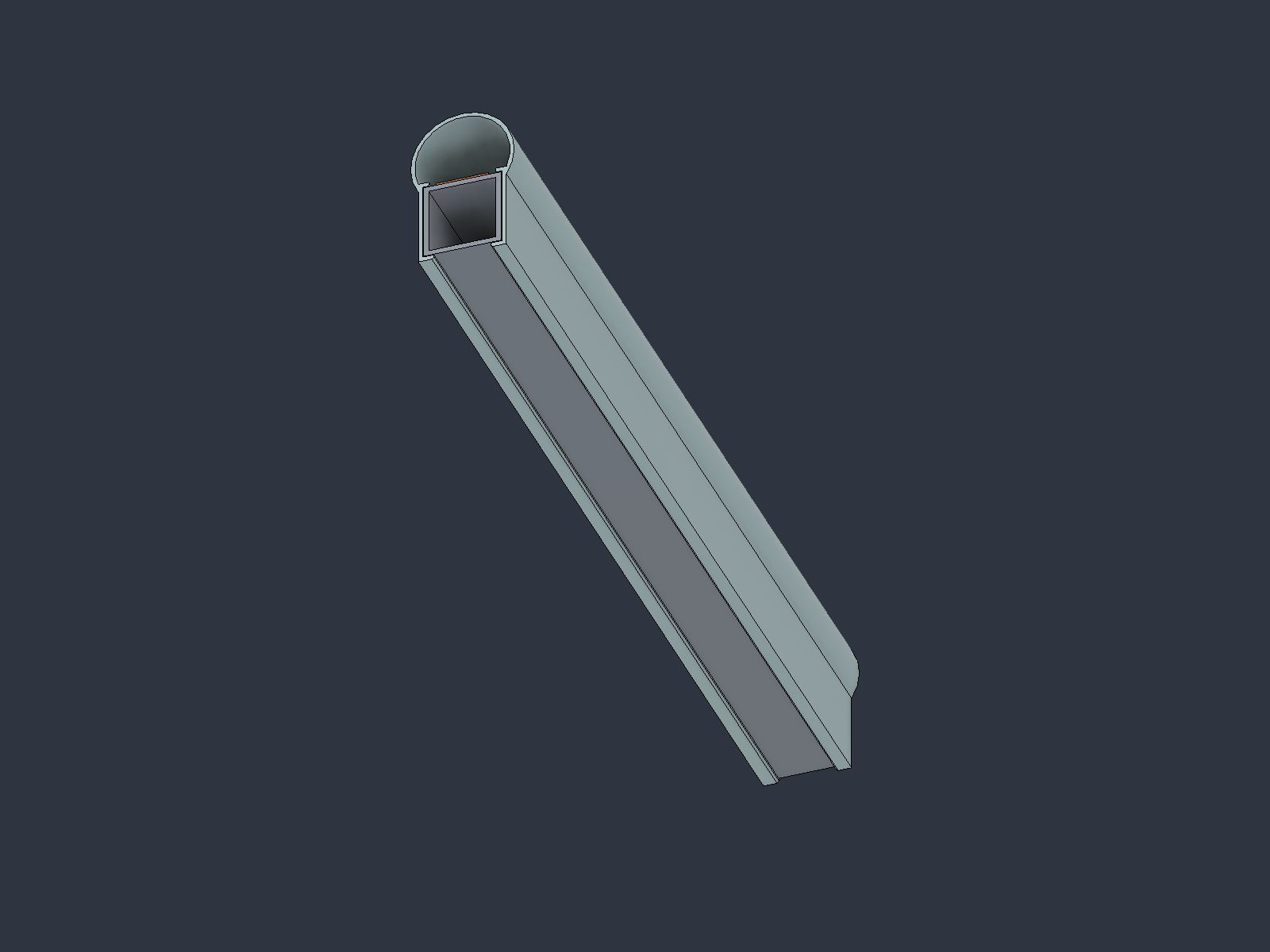
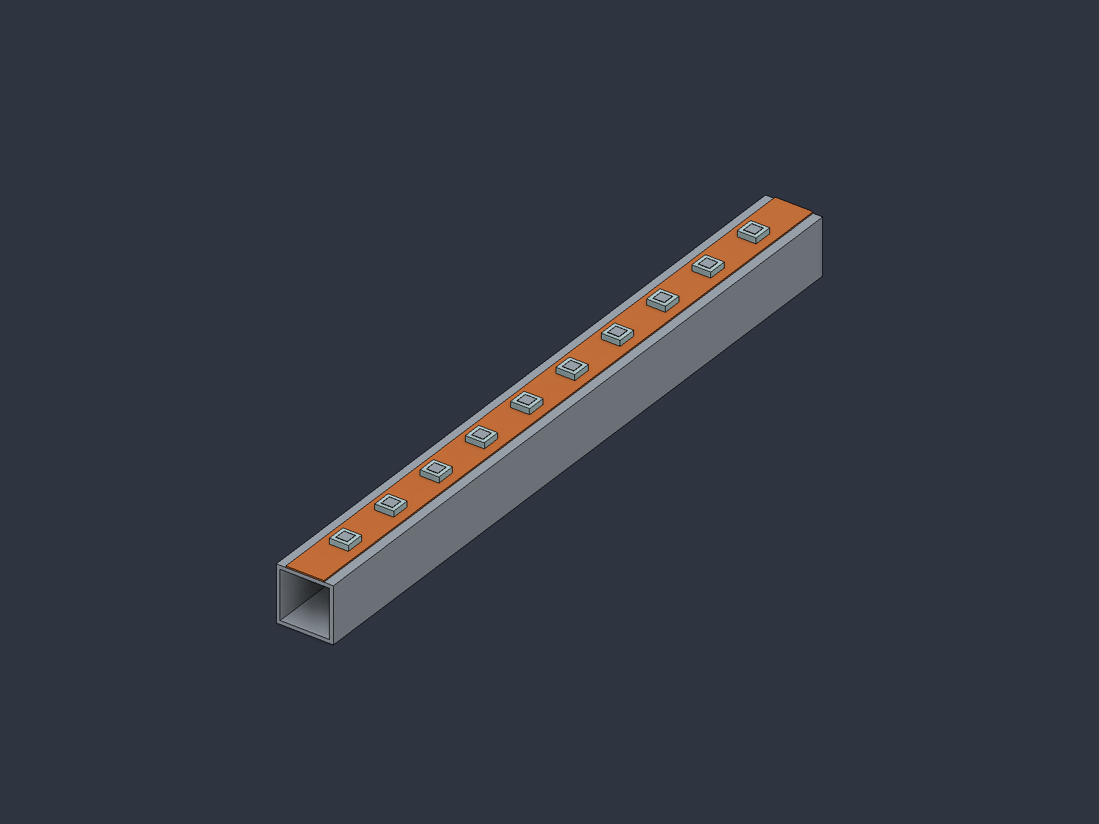
The square-tube diffuser base section was designed by the project owner. CAD refinements and documentation were prepared with substantial OpenAI Codex assistance under owner direction. Physical prototype observations are reported by the project owner; dimensions, fit and lighting of the unbuilt concepts remain provisional.